Could this design use J49/K134 as outputs, perhaps with modifications? I recently came into a small stash of these.

I have tested some more.
It looks as C5 should be 22p.
C1 is still 100p.
Here is the 20kHz squarewave:

It looks as C5 should be 22p.
C1 is still 100p.
Here is the 20kHz squarewave:
I am sure they will work, I have J50/K135 TO3 types and intend to build a channel with both types to check the results. Keep the leads as short as possible between the pcb and the TO3 pins.

yes soldering c5 from bottom would be ideal.
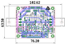
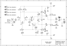
but for a cleaner build, here you go, c5 (c7 in my sch) =22p and c1 (c3 in my sch)=100p.
except for the resistors, which are now RN55D/0.25W package, the same parts guide as posted earlier can be used. zobel is still 1W min, 2W if you can fit it.
but for a cleaner build, here you go, c5 (c7 in my sch) =22p and c1 (c3 in my sch)=100p.
except for the resistors, which are now RN55D/0.25W package, the same parts guide as posted earlier can be used. zobel is still 1W min, 2W if you can fit it.
Attachments
Transitional miller perhaps would be fine for this use case?Well, you stil can try to assemble it and check if it is reasonably stable in practice. But generally you would need to add some compensation here and there, Miller or shunt, depending on you preferences. Yes, the THD, bandwidth and speed will have to be sacrificed. In my opinion (a lot of people will agree, and a lot -disagree) though humble 20-30 v/uS should be well enough for 50 or less Watts amp. And THD anything below .005%@20KHz is (in my opinion) not worth fighting for either, sacrificing stability.
Mant thanks prasi for the updated pcb gerbers - you are a champion around here.
Pcb's ordered - looking forward to any member comments here who might also be building this design, although I am in no hurry.
"Be wary of projects which show signs of being based on theory or calculations or simulations only. Look for prototypes and some indication that the author has actually built what he describes".
Link
Link
I think it is a bit premature to order a PCB of undebugged design. It could be easily built on a protoboard.Pcb's ordered - looking forward to any member comments here who might also be building this design, although I am in no hurry.
As long as the builder accepts the risk that the end 'thing' may not work as intended or at all, it's not a problem.
And seriously, PCBs are $5 for 10 plus whatever level of shipping fee you want to pay. I can't get a pint of beer for less than $10, so it's hardly going to break the bank to test out a new design.
And seriously, PCBs are $5 for 10 plus whatever level of shipping fee you want to pay. I can't get a pint of beer for less than $10, so it's hardly going to break the bank to test out a new design.
Well said avtech 
I already know that a project such as this is unvetted and most likely will have some bugs or possibly be a complete failure, but its your own decision to give it a go or move on.
Add the Gerbers to an existing pcb order, super cheapo 🤑
I already know that a project such as this is unvetted and most likely will have some bugs or possibly be a complete failure, but its your own decision to give it a go or move on.
Add the Gerbers to an existing pcb order, super cheapo 🤑
I have built 2 of lineup's previous designs without a problem, so no guts no glory - we will work it out if there is an issue.
I am in agreement with avtech and Vunce - no harm in trying.
I am in agreement with avtech and Vunce - no harm in trying.
- Home
- Amplifiers
- Solid State
- Scope Design: JFET Input EXICON Output 10 Watt Class A