There is a chance that I will also get on the train, I have k1058 and j162 in stock.Yeh, I will order pcb's as soon as the gerbers appear here - hopefully thanks to prasi's great work.
I have all the components for this simple elegant design which measures well according to simulation by lineup.
I would also say Vunce will be having a go at it.
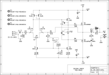
I have changed 2 capacitors and added a Zobel in output.
C1 = 47pF, compensation tested with Scope
C3 = 10uF, not any benefit making it bigger

C1 = 47pF, compensation tested with Scope
C3 = 10uF, not any benefit making it bigger
Thanks lineup for the latest mod, hopefully prasi can incorporate these on his great pcb design with a revised version..
Also I asked you some questions in post #15, can you have a look at that and give us builders your brief answers, thanks again.
Although the added zobel network could be wired off the pcb, the 2 cap value changes would not need any change to the pcb layout.
Also I asked you some questions in post #15, can you have a look at that and give us builders your brief answers, thanks again.
Although the added zobel network could be wired off the pcb, the 2 cap value changes would not need any change to the pcb layout.
Last edited:

Also available slightly cheaper at Audiophonics in France. Altronics here in Oz has the P but not the N. I don't think you will find them in stock as a pair anywhere in Australia - so OS purchase will be required.Looks interesting as always Lineup!
Anyone know where to find some ECX10 over here in Australia? Seems to be unavailable / unobtanium from the usual sellers.
This is the suggested JFETs:
https://diyaudiostore.com/products/matched-jfets
Eventuell you can have to increase the balance potentiometer: R7
R10 should be chosen to give like 2.5mA across the LED
https://diyaudiostore.com/products/matched-jfets
Eventuell you can have to increase the balance potentiometer: R7
R10 should be chosen to give like 2.5mA across the LED
Last edited:
Hello Thimios,Thank you prasi!
You always support us! 🙏
PS. please, if you will find the time post the diy friendly single side pcb in pdf. 😉
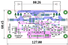
here you go. both diy pdf and gerbers with modified design as per #42.
Attachments
This is the 20kHz square with C1=220pF
I think this is a good value. 47pF is too small.

I think this is a good value. 47pF is too small.
You're so quick! Great layout as always!here are build files and gerbers.
here is a parts size guide for info. i dont have any part numbers.Hello Thimios,
here you go. both diy pdf and gerbers with modified design as per #42.
Attachments
@lineupThis is the 20kHz square with C1=220pF
Forget that virtual oscilloscope. Square wave response of 2 MHz bandwidth amplifier is much better. Here is 100 kHz response from my amplifier with EXICON laterals:
Your amplifier should have the same. 🙂
"The S version has been tested and graded into colour bands based on the technical spec shown below to ensure close matching. We cannot guarantee a specific colour band upon request but orders will be supplied from the same colour band. If you have a particular requirement, please contact us before ordering."
I recommend buying the S version.
ECX10N20-S
ECX10P20-S
I recommend buying the S version.
ECX10N20-S
ECX10P20-S
There is no benefit from S version where single MOSFET per rail is used. S versions are meant for using devices in parallel. It does not provide any P and N channel matching. From the leaflet:
- The test bands are different for N channel and P channel
- There is no benefit from having the same colour dot as the test bands are not the same.
Hi again prasi, is it worth changing the silk screen on your pcb for the value of C3 back to 220pF (was 47pF) as lineup has shown in post #49?
I will wait on your reply before I order my pcb's, thanks.
I will wait on your reply before I order my pcb's, thanks.
I still have a few K170s from my old Plantefeve assembly, but no J113, I must have some J200s somewhere.This is the suggested JFETs:
https://diyaudiostore.com/products/matched-jfets
Eventuell you can have to increase the balance potentiometer: R7
R10 should be chosen to give like 2.5mA across the LED
I repeat.
Buy these JFETs: https://diyaudiostore.com/products/matched-jfets
The balance potentiometer R7 can be necessary to increase the value.
From 10 Ohm to 20 or 50 Ohm.
It all depends on how well matched the JFETs are.
Buy these JFETs: https://diyaudiostore.com/products/matched-jfets
The balance potentiometer R7 can be necessary to increase the value.
From 10 Ohm to 20 or 50 Ohm.
It all depends on how well matched the JFETs are.
- Home
- Amplifiers
- Solid State
- Scope Design: JFET Input EXICON Output 10 Watt Class A