I can get the FFT to display on the scope. I'd like to get the numerical results in a batch rather than moving a cursor and writing down the values manually.
I began using & selling Spec'A's around 1965 but never had a need for a text file of the entire span. Only the peak values are of importance. And their differences.
Just move ahead & do the simple tests first. One set for each condition, with & without the 10K resister bypassed. The scope result at the screen is of great importance. The practice will help you familiarize with your test equipment.🙂
Just move ahead & do the simple tests first. One set for each condition, with & without the 10K resister bypassed. The scope result at the screen is of great importance. The practice will help you familiarize with your test equipment.🙂
jderimig,
Perhaps your scope FFT has 2 cursors.
Set Cursor to FFT Magnitude
Cursor # 1, dB
Cursor # 2, dB
Delta dB of Cursor of # 2 to Cursor # 1.
Put Cursor # 1 on the top of the Fundamental (like a 1kHz test tone)
Put Cursor # 2 on the top of the 2nd Harmonic (like 2 kHz)
Read the Delta -dB.
-46 dB is 0.5%, -40 dB is 1%, -36 dB is 2% 2nd Harmonic Distortion.
Put Cursor # 1 on the top of the Fundamental (like a 1kHz test tone)
Put Cursor # 2 on the top of the 3rd Harmonic (like 3 kHz)
Read the Delta -dB.
-46 dB is 0.5%, -40 dB is 1%, -36 dB is 2% 3rd Harmonic Distortion.
It is that easy.
Last edited:
Actually I was playing with it after I got home. Going through the menu's I found the "table" option. Gives me a table of the magnitude of all the peaks.
Is that table in dB, or dBV?
Sometimes I hate 'dB' because there is no absolute amplitude, the values are only relatative to each other.
Sometimes I hate 'dB' because there is no absolute amplitude, the values are only relatative to each other.
Last edited:
dBV. Confuses the heck out of me too. So that is not a power dB right?
So 2nd Harmonic % is 10^(delta dBV/10)? if it were dBm I would take the square root?
So 2nd Harmonic % is 10^(delta dBV/10)? if it were dBm I would take the square root?
jderimig,
Let me think about providing a more full answer later.
Harmonic Distortion is in terms of the Voltage of the Harmonic, versus the Voltage of the fundamental, expressed as a percentage.
The distortion of 10V of fundamental, and .1 Volt of harmonic is:
100 X (0.1/10) = 1%
Suppose that distortion is all 2nd Harmonic.
10V fundamental, 0.1V 2nd harmonic (1% Harmonic distortion).
20 x Log (0.1/10) = -40dB
The 2nd harmonic is 40dB Less than the fundamental.
Suppose the 3rd Harmonic is also -40dB Less than the fundamental (1% Harmonic distortion)
Then the Total Harmonix Distortion (THD) is:
(*1) Root of (the sum of the squares of the percents). That is called Root Sum Squares, or RSS.
Root (1% squared + 1% squared) = Root (2%) = 1.414 % THD
Suppose the 2nd harmonic distortion is 1%, and the 3rd harmonic distortion is 0.5%.
Plugging those numbers into (*1) above, we get THD of 1.118%
dBV is dB referred to 1 Volt.
Suppose signal is 0.1V.
20 x Log (0.1V/1V) = -20dBV; the signal is 20dB less than 1 Volt.
dBm takes a little more work to understand.
It is dB referred to 1milliWatt.
1 Watt = 1000 x 1 mW.
10 x Log (power in mW/1mW) = dBm
10 x Log (1W/1mW) = 10 x Log (1000mW/1mW) = 30dBm
The thing about dBm, is it relates to power.
But it could be power into 8 Ohms, power into 50 Ohms, power into 600 Ohms.
0dBm (1mW) will be a different voltages into 8 Ohms, versus into 50 Ohms, versus into 600 Ohms.
When using dBm, you need to define the impedance, for example, dBm into 50 Ohms;
or dBm into __x__ Ohms, etc.
Last edited:
Bypassed versus unbypassed results - 1
Results are in from first batch of measurements.
Voltage output at clipping
Unbypassed: 17.6pp
Bypassed: 17.4pp
Input required to drive output to clipping
Unbypassed: 3.7pp
Bypassed: 3.1pp
FFT at 1W output: Unbypassed
Fundamental: 6.6dBV
2nd H : -21.2 dBV
3rd H : -32.3 dBV
FFT at 1W Bypassed
Fundamental: 7.6 dBV
all others at the noise level below -45dbV
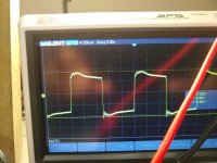
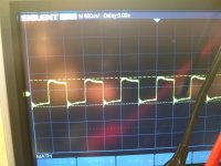
Square waves into speaker: First is unbypassed, 2nd pic is bypassed.
Results are in from first batch of measurements.
Voltage output at clipping
Unbypassed: 17.6pp
Bypassed: 17.4pp
Input required to drive output to clipping
Unbypassed: 3.7pp
Bypassed: 3.1pp
FFT at 1W output: Unbypassed
Fundamental: 6.6dBV
2nd H : -21.2 dBV
3rd H : -32.3 dBV
FFT at 1W Bypassed
Fundamental: 7.6 dBV
all others at the noise level below -45dbV
Square waves into speaker: First is unbypassed, 2nd pic is bypassed.
Attachments
On the FFT I want run it again. Before I did the bypassed by noise levels were about 68db down. When I setup the bypass test I used a clip lead to put the bypass in and out of the circuit so I could do a quick live comparison with the scope. This arrangement may have picked up some noise. I want to repeat with a careful dressing later.
Interesting:
At clipping, output: 17.6(U)/17.4(B) = ~ 0.1 dB Less Power when Bypassed?
Curious.
At clipping, drive required: 3.7(U)/3.1(B) = ~ 1.54 db less drive required when Bypassed.
How can 1 Watt have a fundamental at both 6.5dBV and 7.6dBV?
1 Watt, 8 Ohms, 2.828V
2.828V is 1 Watt into 8 ohms (9.03dBV).
There must be a lot of harmonic distortion in there for the fundamental to be only 6.6dBV or only 7.6dBV.
With no distortion, 1 Watt into 8 Ohms would be 9.03dBV.
Last edited:
When bypassed the output didn't have all that 2nd Harmonic distortion when unbypassed? Or most likely 0.2V is within the measurement system (scope + eyes).
Its not really 1 watt. I set the drive so the output was 8v p-p. I don't have a true RMS meter (although that function is probably in my scope somewhere).
Interesting:
At clipping, output: 17.6(U)/17.4(B) = ~ 0.1 dB Less Power when Bypassed?
Curious.
At clipping, drive required: 3.7(U)/3.1(B) = ~ 1.54 db less drive required when Bypassed.
How can 1 Watt have a fundamental at both 6.5dBV and 7.6dBV?
1 Watt, 8 Ohms, 2.828V
2.828V is 1 Watt into 8 ohms (9.03dBV).
There must be a lot of harmonic distortion in there for the fundamental to be only 6.6dBV or only 7.6dBV.
With no distortion, 1 Watt into 8 Ohms would be 9.03dBV.
Last edited:
8V peak to peak into 8 Ohms is 1Watt (for a sine wave).
8V peak to peak/2 = 4V peak
4V peak x 0.707 = 2.828Vrms
(2.828Vrms)squared / 8 Ohms = 0.996 Watt
I cheated, 0.707 is very slightly smaller than 1/Root(2), so the answer was slightly smaller.
+6.6dBV
-21.2dBV
27.8 dBc 2nd Harmonic
That is 4.07% 2nd harmonic distortion
4% of 4V peak is 160mV peak, or about 113mVrms 2nd harmonic
Last edited:
Ok I found the RMS tool on my scope and reran.
At 2.82V rms bypassed and unbypassed fundamentals were 7.83dBV.
Unbypassed 2nd H was -16.8dBV and was below -40db bypassed
3rd H was ~ -35dBV both cases.
At 2.82V rms bypassed and unbypassed fundamentals were 7.83dBV.
Unbypassed 2nd H was -16.8dBV and was below -40db bypassed
3rd H was ~ -35dBV both cases.
jderimig,
Thanks for running that test.
So . . .
At 1 Watt,
5.87% 2nd Harmonic distortion un-bypassed
versus
Less than 1% when bypassed.
It is interesting that the 3rd harmonic was not changed, at ~ -42.83 dBc about 0.72%.
Sounds like the driver was "foreshortening" in one direction, and the output stage was "foreshortening" in the other direction.
Your data set in poet #88 is very good. Looks like it shews bypassing gives better results, much lower D%. Should look at the waveform on the unbypassed screen, what is the p-p amplitude running a sine wave at One Watt?
The NFB ahead of the unbypassed screen sees that as an error & tries to fix it. That gain is about X1500, goes a very log way to masking a problem at that point in the circuit.🙂
Definitions of DBV & others is given at-
Gain structure: input and output levels - Biamp Systems
The NFB ahead of the unbypassed screen sees that as an error & tries to fix it. That gain is about X1500, goes a very log way to masking a problem at that point in the circuit.🙂
Definitions of DBV & others is given at-
Gain structure: input and output levels - Biamp Systems
I will install the bypass caps and give a listen this weekend. Since the Schade doesn't have to work as hard with the bypassed scr R should I reduce in steps and see what happens? (I presume you might suggest one step.)...
The main fault in the cct is/was the unbypassed screen resister. Since that is resolved almost any combination if Schade & Full Loop FB could be tried. My personal preference is no Schade at all since it can cause PS hum problems. And more than enough ordinary FB can be applied to get the best result.
But before you leave the screen issue get a scope shot of the voltage on the screen without bypassing at One Watt & 5W. That information is not only nice to have but can be used to explain the issue in more detail. The information will also be useful when you go PP.
You could also determine your loudspeaker resonance issues with an easy setup. With the speaker driven at low level from the amplifier thru a suitable resister, say 100R, the resonance can be seen on the scope as the SG is slowly swept from 20 Hz & up. The scope probe goes on the loudspeaker leads, not the amp.
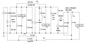
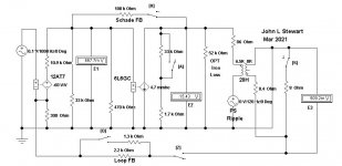
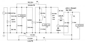
The attachments are the bare bones numbers for no FB, Schade FB, Full Loop FB & Both FB. A guide for you as you try different FB.🙂
Be sure to keep a record that you can refer back to.
But before you leave the screen issue get a scope shot of the voltage on the screen without bypassing at One Watt & 5W. That information is not only nice to have but can be used to explain the issue in more detail. The information will also be useful when you go PP.
You could also determine your loudspeaker resonance issues with an easy setup. With the speaker driven at low level from the amplifier thru a suitable resister, say 100R, the resonance can be seen on the scope as the SG is slowly swept from 20 Hz & up. The scope probe goes on the loudspeaker leads, not the amp.
The attachments are the bare bones numbers for no FB, Schade FB, Full Loop FB & Both FB. A guide for you as you try different FB.🙂
Be sure to keep a record that you can refer back to.
Attachments

Last edited:
I may not get those screen measurements right away, I am having too much enjoyment listening to the amplifier. Its sounds better with some 'edge' taken off by the bypassed screen resistors.
I still can't believe that "we" made an SE amp with no measurable 2nd order harmonic distortion. (at 1W, 1khz)....
I still can't believe that "we" made an SE amp with no measurable 2nd order harmonic distortion. (at 1W, 1khz)....
- Home
- Amplifiers
- Tubes / Valves
- Schade P2P and gNFB in RH807