Many scopes FFT are only 8-bit resolution, 48 DB. The FFT I use is a Pico Tech thing that hooks up to a PC via USB, it is 2-channel, 10 MHz, 12-bit so 72 DB. It would probably shew quite a bit more harmonics on your amp. 72 DB is usually enough for most tube amps.
I've another 16-bit Pico Tech but not as handy to use. And a 2-channel, 12-bit 250-MHz thing, but seldom use it. Has many built in SG functions as well.
All dump files to-the PC so very good for reports.
I've another 16-bit Pico Tech but not as handy to use. And a 2-channel, 12-bit 250-MHz thing, but seldom use it. Has many built in SG functions as well.
All dump files to-the PC so very good for reports.
It is still true 2nd H is below my measurable distortion. Is it unusual to have 2nd H much lower than 3rd H away from clipping?
Yes, with the screen bypassed the 2nd harmonic dropped below the 8bit resolution of my scope. But the 3rd stayed about the same.
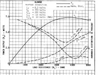
The load mismatch is probably the main factor in the distortion numbers you are seeing. Any of the Olde text books on toob tech shew rapidly rising D% for pentodes if there is a mismatch either way from optimum. This one attached for the 6L6GB is a good example.
Does your OPT have a 16R output tap? If so, try that while driving the 8R load.
But if the amp sounds OK, that is what matters. However for good design, the published specs need to be followed. Not the advice of some unknown guru, throwing darts till it works.🙂
Does your OPT have a 16R output tap? If so, try that while driving the 8R load.
But if the amp sounds OK, that is what matters. However for good design, the published specs need to be followed. Not the advice of some unknown guru, throwing darts till it works.🙂
Attachments
I think there is a disconnect. The distortion is quite low not high. Especially 2nd order. I thought SE designs had more second order distortion than 3rd. This one looks like a PP amp not an SE amp.
The original designer called for a 6K primary impedance. I thought this was a bit high, other 807 designers shoot for ~5K in SE (for some reason). However my reference speakers are about 6ohm for most of the spectrum. So a 6 ohm load with a 6500 primary would give about 4875 to the plates.
The original designer called for a 6K primary impedance. I thought this was a bit high, other 807 designers shoot for ~5K in SE (for some reason). However my reference speakers are about 6ohm for most of the spectrum. So a 6 ohm load with a 6500 primary would give about 4875 to the plates.
The graph in Post # 105 shows 250V plate, 250V screen, -14V grid bias,
and 10Vrms signal (14.14V peak).
That is a classic Quiescent state (among many Q states).
It should be noted that the graph represents the performance of a 6L6WGB.
There is no driver distortion, no output transformer distortion, no output transformer insertion power loss, no local negative feedback, and no global negative feedback.
Just only Bare Bones 6L6WGB performance at those Quiescent conditions.
The 6L6WGB is maxed out in Class A1 for those particular Quiescent conditions, since anymore drive to the grid will draw grid current (actually, the peak grid voltage is is 0.14V more positive than the cathode (there will be a very small grid current, during the signal +peak).
Any drive voltage that is more than 10Vrms, will become Class A2. And eventually with drive level increasing enough, the tube will go into cutoff at one end of the sine wave.
Cuttoff sounds horrible, when the output stage is single ended.
For that graph:
The point where 2nd harmonic distortion = 3rd harmonic distortion is when the plate load, RP, is approximately 3350 Ohms. The 2nd and 3rd distortion % is the same at that load impedance.
The harmonic distortion of the 2nd (4.6%) and 3rd (4.6%) with the 10Vrms drive, about 6.5 % "THD" (I did not include the low level 4th harmonic distortion in that "THD" calculation).
But . . .
2nd harmonic distortion goes at a rate of 2:1 versus drive level, which is a relative rate of
1:1.
And . . .
3rd harmonic distortion goes at a rate of 3:1 versus drive level, which is a relative rate of 2:1.
If you reduce the 10Vrms drive signal to only 3.16Vrms, the 2nd harmonic distortion will be reduced by 10dB; and the 3rd harmonic distortion will be reduced by 20dB.
They were equal before, so . . .
That means when the load is 3350 Ohms, the 2nd harmonic distortion will be 10dB more than the 3rd harmonic distortion at that drive level (3.16V).
That is what you were expecting, Dominant 2nd harmonic distortion. Right?
Your amplifier has driver harmonic distortion, output transformer harmonic distortion, output transformer insertion loss, and you have some Schade (local) negative feedback, or you have some global negative feedback, Right?
I mention the transformer insertion loss, because builders often complain of getting less output power than they expected.
A typical inexpensive or medium cost output transformer might have an insertion loss of 0.5dB to 1 dB.
If the 6L6WGB puts 7.25 Watts out (from the graph with 3350 Ohm primary) into a transformer that has a 1dB insertion loss, you only get
5.8 Watts out of the secondary to the load.
Have fun listening to your amplifier.
Last edited:
I don't think I am going to make anymore measurements for a while, I don't want to disconnect my speakers from it. I am enjoying it too much.
I have one more "tweak" in mind and that is to replace the OT ww cathode resistors with non-inductive ones.
I have one more "tweak" in mind and that is to replace the OT ww cathode resistors with non-inductive ones.
If you have the output tube cathode resistors very well bypassed with very good capacitors, then the performance of the inductive and the non-inductive resistors in those spots should be the same.
The capacitor's capacitive reactance in series with the capacitor's ESR, has an impedance low enough to "short out" the inductive reactance of the wirewound resistor (at audio frequencies).
Just my optinion.
The capacitor's capacitive reactance in series with the capacitor's ESR, has an impedance low enough to "short out" the inductive reactance of the wirewound resistor (at audio frequencies).
Just my optinion.
I am using these (47uf) on 400ohm resistor. Are these good?
https://www.mouser.com/datasheet/2/293/e_ukz-1513448.pdf
https://www.mouser.com/datasheet/2/293/e_ukz-1513448.pdf
47uF at 20Hz has 169 Ohms of capacitive reactance.
I imagine a quality audio cap like would have less than 1 Ohm ESR.
Seems good enough to me.
Come on cap experts, how good or bad is that cap for bypassing a 400 Ohm self bias resistor that may or may not be inductive)?
I do not have an inductance meter for the various wirewound self bias resistors that I use.
A good argument can be made for using the largest value cathode bypass caps that can be fit. Good electrolytics are cheap enough these days that the constraints from the past don't apply.
1) The larger the cap the less voltage appears across it. Less voltage, less distortion. The limiting case is no voltage, so no distortion.
2) Cap values shouldn't contribute a pole/zero pair into the mix without a very good reason. For feedback amplifiers it's especially important to get these moved as far as possible from the dominant high pass pole.
YOS,
Chris
1) The larger the cap the less voltage appears across it. Less voltage, less distortion. The limiting case is no voltage, so no distortion.
Less AC volts, not DC.🙂
Less AC volts, not DC.🙂
Arf! But what is the distortion of DC? In the forest, with the Pope's bear.
More is more, and 470uF and 1000uF caps are commonly available now.
YOS,
Chris
More is more, and 470uF and 1000uF caps are commonly available now.
YOS,
Chris
I overlooked the best the amplifier could be, with more capacitance.
Agreed, we need more capacitance, so we can bypass those self bias resistors, for that 6Hz canon in the Telarc recording of the 1812 overture.
Never mind the output transformers, and the woofer, and the small room that can not set up a standing wave for 6Hz.
Peel the layers off the onion, one at a time.
Arf! But what is the distortion of DC? In the forest, with the Pope's bear.
First term of the Fourier expansion, Zero H. Some people call it rectification. All amplifiers have it to a degree, causes shift in the operating point as the signal level changes. But it can't get thru the OPT anyway.
But I Digress!!😀
First term of the Fourier expansion, Zero H. Some people call it rectification. All amplifiers have it to a degree, causes shift in the operating point as the signal level changes. But it can't get thru the OPT anyway.
But I Digress!!😀
1. Now the fixed bias proponents can chime in.
With fixed bias, there is no bias shift with large signals (on those self bias resistors with bypass caps, because they have been removed).
And so, there is no bias shift at all with fixed bias on large signals (until the grid draws grid current on the cap in the RC coupling circuit).
2. And now the DC coupled proponents can chime in.
With DC coupling, there are no bypass caps, and no coupling caps. So no change in bias with large signals.
And there is no DC shift (Well, until a tube heats up, drifts, line voltage changes that causes a change to the filament voltage, a tube ages, etc.).
All topologies require attention to details.
Failure to pay attention to the details of any given topology, causes failure of that topology to perform at its best.
just one man's opinion.
Last edited:
The cathode R is not what you should concentrate on bypassing. It is the cathode itself. Approximated by 1/transconductance...tends to deliver a larger bypass cap.
cheers,
Douglas
cheers,
Douglas
Same kind of fix applies to screen bypass. The resistance part of the calc needs to include rg2, usually not even considered. For small signal pentodes like the 6AU6 rg2 is ~30K, I measured a few years ago. Not sure about 6L6 but probably 1/10th of that.🙂
- Home
- Amplifiers
- Tubes / Valves
- Schade P2P and gNFB in RH807