Same kind of fix applies to screen bypass. The resistance part of the calc needs to include rg2, usually not even considered. For small signal pentodes like the 6AU6 rg2 is ~30K, I measured a few years ago. Not sure about 6L6 but probably 1/10th of that.🙂
Not sure at all...the 6AU6 has a rather large percentage of cathode current going to the g2. 3-4:1 with the plate above the g2 voltage. EL84 is much less, and IIRC 6L6 also lower. This becomes important for resistively loaded signal amplifier stages. How is this g2 current related to its resistance?
cheers,
Douglas
Lots of good points already, but I'd argue that larger than commonly (historically) used bypass caps are also better for bias stability. Not as good as "fixed" adjustable bias, but approaching it. Even in class A, as JHS points out, nonlinearitys cause DC current to vary some with signal level.
What is the best choice for the time constant of this bias pump? We humans average senses' amplitudes in the 1/4 second range (give or take a lot) so probably the time constant should be as far from that as possible.
Thoughts?
YOS,
Chris
What is the best choice for the time constant of this bias pump? We humans average senses' amplitudes in the 1/4 second range (give or take a lot) so probably the time constant should be as far from that as possible.
Thoughts?
YOS,
Chris
We humans average senses' amplitudes in the 1/4 second range (give or take a lot) so probably the time constant should be as far from that as possible.
At my age the response time is about a day. So I'll post some real experimental data tomorrow on rg2 measurements & results.🙂
At my age the response time is about a day. So I'll post some real experimental data tomorrow on rg2 measurements & results.🙂
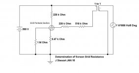
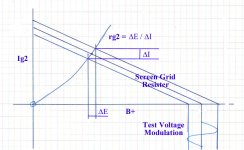
Determination of Screen Resistance
How I tested a small signal pentode a few years ago. A driving signal is introduced to the screen lead & the resulting deltas of E & I measured thru a high impedance differential probe. Without repeating the math the result was 29K.
So to estimate the bypass cap the R used would need to be 29K in parallel with the screen supply resistor.🙂
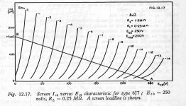
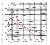
The screen family of a small pentode, the 6J7 are lifted from the pages of RDH4.
How I tested a small signal pentode a few years ago. A driving signal is introduced to the screen lead & the resulting deltas of E & I measured thru a high impedance differential probe. Without repeating the math the result was 29K.
So to estimate the bypass cap the R used would need to be 29K in parallel with the screen supply resistor.🙂
The screen family of a small pentode, the 6J7 are lifted from the pages of RDH4.
Attachments

With the improvement of bypassing the screen resistor I was wondering if further gains can be made by regulating the screen voltage? Or is this past the point of diminishing returns?
At this point any further improvements would qualify with 'Gilding the Lily'. The Law of Diminishing returns sets in very quickly. If we throw enough money at a project, anything is possible tho!
Easy to try varying the NFB on both Schade & Full Loop. Check if it is possible to notice any differences in sound quality. Bottom line after a certain point is reached in the amp is set by the speaker & the environment.🙂
Easy to try varying the NFB on both Schade & Full Loop. Check if it is possible to notice any differences in sound quality. Bottom line after a certain point is reached in the amp is set by the speaker & the environment.🙂
I think I am done. Speakers are my next project, thinking of the Troels DTQWT.
However I did swap out the coupling cap for ruskie PIO caps and it seemed to make an improvement.
Before vocals had a slight edgy coloration that was constant on almost all recordings, so it was a coloration. It seems to be much reduced with Ruskie caps. I am thinking the 12AT7 and/or 807 may have been generating a little RF (which they are famous for). Perhaps the Ruskie caps reduced that? I dunno. Anyways, on to SPEAKERS!

Bandersnatch,
The cathode impedance of 1/transconductance only applies when the plate is driving
Zero Ohms (like in a cathode follower). [transconductance, Gm]
For a triode, the cathode impedance is: (1/Gm) in series with (RL/u) [RL = plate load]
Example, if Gm = 1000uMhos, u = 20, and RL = 20,000 Ohms.
1/Gm = 1000 Ohms; RL/u = 1000 Ohms.
Cathode impedance = 1000 Ohms + 1000 Ohms = 2000 Ohms.
You have to bypass the impedance of 2000 Ohms that is in parallel with the self bias resistor, Rk Ohms.
If the self bias resistor is 2000 Ohms, and the cathode impedance is 2000 Ohms, you need to bypass 2000 Ohms in parallel with 2000 Ohms, and that is 1000 Ohms needing to be bypassed.
By the way, if the capacitive reactance at 20Hz = the parallel impedance of 1000 Ohms, that gives the -3dB rolloff at 20 Hz.
But if you double that capacitance (1/2 the capacitive reactance), it gives the -1dB rolloff at 20Hz.
That bypass -1dB rolloff at 20Hz, and a -1dB rolloff at 20Hz from the RC coupling from driver to output tube grid, and a -1dB rolloff at 20Hz of the output transformer will give a -3dB rolloff at 20Hz for the amplifier. It will all add up quickly.
You would not line up those rolloff frequencies for amplifiers that use global negative feedback, but it would be OK for an all triode, or triode wired pentode/beam power SE amplifier that does not have any global negative feedback.
I will let someone else give the model for Pentode tubes and Beam Power tubes.
Last edited:
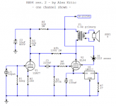
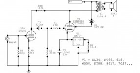
See the attachment. The original used an EL84, not a 6L6 as the output. That is why the OPT in your version at 6K is mismatch. The 10K resistor was a 24V Zener, both significant differences from the original.🙂
I wasn't building the RH84 amp. I built the RH807SE, right to the schematic.
I wasn't building the RH84 amp. I built the RH807SE, right to the schematic.
That may well be. But the schematic you used has two gross errors anyway.
That may well be. But the schematic you used has two gross errors anyway.
RH Universal
Setup for higher power toobs such as 6L6 & others. 2.5K OPT & Zener supply for g2 of the 6L6. And a link to all Alex Kitic's thoughts.🙂
RH Amplifiers: RH Universal
Setup for higher power toobs such as 6L6 & others. 2.5K OPT & Zener supply for g2 of the 6L6. And a link to all Alex Kitic's thoughts.🙂
RH Amplifiers: RH Universal
Attachments
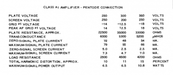
That data refers to the ordinary 6L6 series, 19W plate dissipation. It shews the D% rather high, not a good starting point for fidelity. The RH Universal schematic lists several tubes with higher dissipation specs, the 6L6GC is good for 30W. Based on that I plotted a 3K loadline on the G2 curves for the 6L6GC. The idle current would be ~80 mA while total plate voltage from cathode to plate about 300. That allows something like 30V lost in the cathode bias resister & resistance of the OPT primary.
There is no ideal Rl for a pentode, the published numbers give the max power Rl for a resistive load. A real load isn't much like that at all & spends most of the time looking like an ellipse. Clipping happens much sooner than on a resistive load. Since most speaker systems have an impedance rise both above & below mid frequency that dictates that a loadline of lower impedance will give better performance. So 2.5K is a very good starting point for the power supply used.
Others may differ, but if they do we need more than opinion as an answer.🙂
Attachments
Thanks for that. I drew one too at a 5.5K load line. Why pound that poor little 807 at 80% of its dissipation rating at idle? That sounds cruel. With a 5.5k line I can dial back the bias to about 55ma running at 60% Pd max. The tube will be happier and the power output penalty is very very small. (and less impact on climate change!) And I am measuring less than 1% THD now.
Last edited:
Less than One % distortion is nice but that is after all the NFB that is in the cct. A good design starts out with low D%, not after a lot of NFB. But if it sounds OK, that is what matters.🙂
Agree. But that is water under the gilded lily now. I am not about to spend another $200 to see what 3.5K OPT sound like. That can wait for my next balanced 807 amp project.
Less than One % distortion is nice but that is after all the NFB that is in the cct. A good design starts out with low D%,
In order to minimize the distortion of the system shouldn't both the load lines of the driver and the output tube be considered? Especially if you wanted to take advantage of possible complimentary distortion cancellation offered by a selected driver-output tube pairing. As such the optimum OT load line would not be achieved by considering the OT plate characteristics alone, no?
I don't know if the designer considered this but I may try a few sims along this line.
That may well be. But the schematic you used has two gross errors anyway.
Speaking of errors, I was just in my amp swapping out some resistors and I discovered I never had the Schade FB resistor connected! So I was just running on the 6db or so gNFB.
Haven't decide whether to hook it up and test listen with it...
A 3.5k to 8 Ohm transformer, and an 8 Ohm load resistor, presents 3.5k load to the output tube across most of the audio frequency band.
But, put an 8 Ohm loudspeaker that presents an impedance ranging from 6 Ohm minimum to 40 Ohms maximum, and the load impedance to the output tube will be all over the map.
Know all the impedance dips and peaks of your loudspeakers across the audio frequency range, before you pick the best primary impedance for your output tube.
Or, stop worrying about it.
- Home
- Amplifiers
- Tubes / Valves
- Schade P2P and gNFB in RH807