I think the root of my confusion is the B+ voltage ra7 uses for the SCG.
I have assumed that is needed to drive the SIT followers.
Is that where I am going wrong in my readily admitted uninformed thinking?
I have assumed that is needed to drive the SIT followers.
Is that where I am going wrong in my readily admitted uninformed thinking?
Yeah, the B+ voltage is the DC voltage and has nothing to do with the amount of gain.
If your speakers are, say, 100 db/W (Klipsch Jubs?) and given your listening preferences (90 db average with 15db music peaks), I would guess you don’t need more than 1-2W of power. Now looking at the table, you only need 3Vrms or so for 1W of power output. If your DAC outputs 5Vrms, then it will drive the follower with enough volume for you.
If your speakers are, say, 100 db/W (Klipsch Jubs?) and given your listening preferences (90 db average with 15db music peaks), I would guess you don’t need more than 1-2W of power. Now looking at the table, you only need 3Vrms or so for 1W of power output. If your DAC outputs 5Vrms, then it will drive the follower with enough volume for you.
Sorry for creating so much confusion here and taking the thread away from its intentions.
My confusion is in understanding the relationship between gain of the system and the peak to peak aspect.
I worry that simply using the DACs would introduce compression with the TDV.
I am using the Klipsch K402 horn but not as a Jubilee - it is an MEH and is bi-amplified. So the sensitivity is very high with no passive crossover in the chain.
Of course, I will finish the SCGs and hear what happens. I hope using a 5k resistor instead of 1k does not harm the sound. If it sounds funny I can always use the specified resistor and continue with the attenuation required when using the Singing Bushes. with 5k I could reduce the attenuation slightly.
As usual I am guilty of trying to be too clever! Without the requisitite knowledge of how all of this fits together, I do think as more folks discover that DSP is not sonic disaster there could be a need for something that does what I would like to do. As far as I can tell there is nothing I can do to reduce the gain within the Xilica DSP. I am using AES EBU input and output so there is no way to use an L pad to reduce the level of the signal going in or out. Attenuating the output of the SCG just so I could have less attenuation within the DSP would seem to be a silly thing to do. Even though if it wold not be I would appreciate being told that!
Compromise is inevitable
Thanks to all and certainly gratitude to ra7 for his work.
No worries, Rick.
The key thing to find out is: how much voltage is needed to make your most dynamic recording (max db range) play at the level you desire. Pano’s thread gets at exactly this question:
https://www.diyaudio.com/community/...h-voltage-power-do-your-speakers-need.204857/
Run the test and find out for yourself.
Let’s say you ran the Pano test and found you need 2.83V max. The TDV has no no gain, so what you feed it is what comes out. So, before the TDV, you will need 2.83V to get your desired volume.
If you use a power amp with gain, say, 20db gain, which is 10 times, then you would need to feed that amp only 0.283V to get 2.83V at the speaker out.
Same applies to the SCG. You can use it but then whatever comes before it would only need to output 0.283V because the default gain of the SCG is 10X or 20 db.
I would shoot for at least 3-6 db of of headroom beyond what you need at the speakers. So, if you find 2.83V is all you’ll ever need, then I would shoot for having a capability of 6V.
Peak to peak and RMS are important things to know. Many explanations on the web.
(BTW, I am well versed in DSP and have been using it for more than a decade. I started with miniDSP but then graduated to doing it all in the computer. There are no limits in the computer. I strongly prefer to not split the signal into multiple amps, especially after knowing about H2 phase importance and how the harmonic spectrum affects the sound. Right now, there is only mild processing to clean-up of the speaker response in the computer but in the past I’ve used full FIR processing and mid-side EQ, inspired by Wesayso’s findings. Using the 15” 2226J and 2431H on the 2384 horn, crossed passively)

Yeah, have been thinking about improving it. Thinking about the 3” Be dia OR the 2452 with aquaplassed or the 4” Be dias. All options =💰
I think the addition of SCG would sound better than just depending on a usually wimpy DAC output stage.
When you mentioned the similarity to the sound you hear from the 10Y I thought I had to try it!
I have no choice but to bi-amplify since a passive crossover for an MEH is well beyond my capabilities.
The unequalized response of the Celestion AXI in the K402 is such that I cannot imagine that being made usable with a passive crossover. There is a huge hump around 1 to 3 KHz and then the top octaves drop off.
With the level of recorded energy in the top two octaves I have found boosting there to be sonically benign and the distortion as measured by REW, I use these measurements as comparative since I have no idea how accurate they are.
Around 6 db of gain with a low Q filter for the top octaves centered at 20 KHz. Almost 20 dB of attenuation around 1 to 3 Khz. From memory.
On the bottom side there are huge peaks in the woofer section. Response grops like a cliff at 400 Hz with peaks at approx 1.2 KHz and around 2KHz requiring 20 dB of high Q attenuation. This is due to the loading not the woofers used.
The woofers and the CD are in phase. Crossover slopes are made with DSPs.
At one meter from the throat there is less than 100 degrees of phase change from 100 to 20KHz. A smooth descent from bottom to top.
I will try Pano's test even though I worry that test tones do not reveal what is needed for dynamics but I guess it would give an idea of averages. I have connected a volt meter to the speaker terminals while playing music and the numbers are impossible to keep up with.
Maybe Hiraga could have come up with a great passive crossover for an MEH, thinking of Pano's association with the great man.
I remember Richard Heyser saying that striking a match results in something like 1000 acoustic watts and would be impossible to reproduce accurately. Now none of us listen to stuff like that but it does indicate that having sufficient power for transients is one of the keys to realistic sound in the home.
Does anyone remember that issue of AUDIO magazine that had his system on the cover? The man believed in amplifier power! The system was all mutli amplified horns. This was in the age when HORNS ARE BAD was all of the rage. i remember thinking that thing must have sounded horrible with all of those high power solid state amps and horns. I ahve no memory of whose amplifiers and I do not think the speaker drivers were mentioned but this was some forty years ago.
Obsession and compromise are always in conflict.
Hi,
Way back when I placed my order from mouser, the particular in4007 diode which was called for wasn't available. I have some of these in my stash. The only relevant difference that I can see is that the parts listed in the BOM have a 1.0V forward voltage and the parts I have on hand have a 1.1V forward voltage. Would it be okay to sub the ones I have on hand?
Thanks,
Alan
I have used the IRF9640 in my test board, but I don't have any FQP12P20's to compare them to. I have been using the FQP9P25's in my builds both vacuum tube and solid state with good results. Maybe just my imagination but I think they sound better than the IRF9640's. The FQPF9P25 is the same part in an insulated case.IRF9640pbf good substitute for FQP12P20?
As for the 1N4007's you won't notice the difference between the two. If you are ordering parts anyway, look for some UF4007's. They tend to be a little less noisy in situations where cheap transformers without snubbers are used.
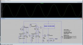
The B+ voltage determines the maximum output voltage swing that the stage can output before clipping sets in. So why did I just build a little breadboard with two sets of cascaded SCG stages that will run on 625 volts?I think the root of my confusion is the B+ voltage ra7 uses for the SCG.
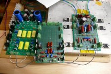
I'm working on a source follower output stage that will need about 600 volts peak to peak of drive voltage to put 50 watts of audio into my 600 ohm OPT's that were intended for vacuum tube use.
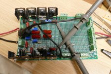
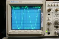
Back in post #63 I mentioned a magazine article that I wrote about some efficiency improvements I made in a vacuum tube cathode follower amp back in 2007. I have always wanted to revisit this design, but never got back to it. I thought that vacuum tubes would be my technology of choice, but now I find myself with a board full of mosfets. I have already tested the pair of two stage SCG drivers to 450 volts where they produce over 400 volts peak to peak. I'm about to populate the follower stage, but progress will halt soon for a Super Bowl party at a local marina.
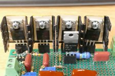
Without some efficiency improvements the board will melt in a minute or so since there is about 115 watts of dissipation in the output FET. A stereo amp would need a few FETs and a really BIG heat sink.
Attachments
Last edited:
If you have them hand, use them. George has some good perspective above.IRF9640pbf good substitute for FQP12P20?
Or is there better?
Thanks
@aljordan yeah, those should work.
@Tubelab_com look forward to more power with less heat. I read your article and as I understood, it would dynamically adjust the B+ on the output. Should work here too and reduce the heat dissipation.
Thanks for that, Tubelab. I know that gain and voltage swing are two separate things but their interrelationship seems to elude me.
In the the future I might try the basics of SCG by eliminating the first follower stage and converting the gain stage to a follower to retain the voltage swing and allow the excess gain in the components preceding it perform gain duties.
Hoping ra7's choice of mosfets will still retain the sound quality of SCG.
Until then I am hoping in a week to have SCG operating with TDV amps.
Look at it this way. Imagine a building out in the desert somewhere where the temperature is HOT. Inside the building is a machine that extrudes some kind of pliable material into whatever width you want. The material comes in a one foot wide width and the machine has a knob called "GAIN" that can squeeze out anything from a few inches to several feet in width. Set the gain on 10 and you get a 10 foot wide slab from the machine. Set the gain on 0.5 and you get a 6 inch wide slab. The internal make up in this machine controls the range of available gain. The gearset that controls the aperture of the extrusion horn is the set of feedback resistors on the gain fet. The size and make up of the machine's internal passages impose limits on the range of gains and the overall extrusion speed.Thanks for that, Tubelab. I know that gain and voltage swing are two separate things but their interrelationship seems to elude me.
In the the future I might try the basics of SCG by eliminating the first follower stage and converting the gain stage to a follower to retain the voltage swing and allow the excess gain in the components preceding it perform gain duties.
Hoping ra7's choice of mosfets will still retain the sound quality of SCG.
The slab travels down a conveyor belt to the door of the building where it exits onto a flatbed trailer. The door can be opened to any width within reason. As long as the door is open wide enough to pass the width of the exiting slab, there is no problem. The slab goes onto the flatbed trailer. If the door isn't wide enough, "clipping" will occur. Some of the extrusion will be "clipped off" on both sides. This door width is the power supply voltage. As long as it's high enough to support the gain and overall width of the slab, the system will work fine.
We could just leave the door wide open, running our machine at any gain and width we want, but remember we are in a desert and all that heat will come inside and fry our machine as it's made of silicon, so we want the door open just wide enough to avoid clipping without allowing too much heat.
The machine must be centered in the doorway or one side of our slab will hit the door frame before the other, limiting our slab width unnecessarilly. We need to keep our machine centered in the doorway, so we have a knob called "BIAS" or idle current, that can adjust the centering.
We test our machine / doorway setup with a constant width slab (sine wave) but remember that it makes a rather complex shape whose width is constantly changing. We need a little extra width in the door (headroom), and a possible offset in the machine bias to accommodate whatever slab profile (music) and flatbed trailer (speaker system) that comes our way.
We can see that the gain and headroom are intertwined but rely on totally different mechanism.
The original quest that led me down the common grid / common gate path was an attempt to get triode like curves from a pentode tube or mosfet. The original work on this idea goes all the way back to the late 30's in a paper published by Schade. He proposed adding feedback from the plate of the tube to the grid to get triode like curves from the new 6L6 pentode tube. Most of his proposals attempted to put the feedback and the drive signal into the same element (the grid) of the tube resulting in imperfections due to the varying impedances involved when the two signals met.
Ham radio operators in the 50's found that grounding the grid of the amplifier tube and feeding the signal into the cathode worked well and provided a method to "cheat" the "maximum DC input power to the final RF amplifying device" rule imposed by the FCC at the time. My work with UNSET simply combined those two approaches.
The first follower stage is a method of getting the signal into the cathode / source with minimal distortion. A transformer will work as well. This allows the gain stage to work as a common gate amp for the audio signal, and a common source amp for the feedback signal. This combination produces near ideal triode curves which is what imparts the "Single Ended Triode" like sound. You may find that changing the topology imparts a significant change in the design's "sound" signature.
I have gone pretty far in the "increasing the gain" direction without negatively affecting the sound. It may be possible to go just as far in the "lower the gain" direction too, but I have not been there.
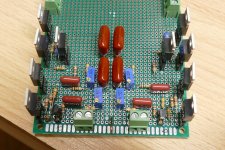
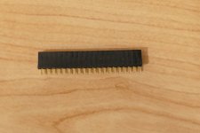
You can get these connectors that are popular with the Arduino community. They will fit right into the SCG board and allow plugging in ant TO-220 fet available. I have seen them in three pin sizes, but I just get the long strips from Amazon and cut them up with wire cutters.
The three pin socket for the TO-92 device is just a piece cut from an 8 pin DIP IC socket. Use a machined pin socket. I have seen strips of these on Amazon as well but didn't have any at the time I decided to "shrink the SCG board."
I have a fair collection of mosfets to try, and another smaller collection of J-fets and BJT's. Some are 30 to 40 years old.
Attachments
Last edited:
Is there a love button for posts? The one above needs it.
George, link to the sockets? At some point, Vunce had provided a link but I don’t know where it is in this thread.
George, link to the sockets? At some point, Vunce had provided a link but I don’t know where it is in this thread.
@ra7 are you looking for these sockets - https://www.amazon.com/dp/B0778TFL39?psc=1&ref=ppx_yo2ov_dt_b_product_details. I got these to test the jfets but seems like we can use even the to220 mosfets too.
Thanks
Thanks
Thanks, I have those but they don’t work with the flat to-220 pins. Have you tried to-220 with those? What George is showing accepts to-220 pins. I have seen Vunce use them too.
Tubelab, that was masterful. Beautiful, even.
Not often is one given such conceptual clarity.
We are lucky to have you in this kooky hobby!
Not often is one given such conceptual clarity.
We are lucky to have you in this kooky hobby!
- Home
- Amplifiers
- Pass Labs
- Schade Common Gate (SCG) Preamp