
Nice! Yours is much neater than mine.

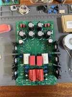
Trying to test a push-pull output buffer (no degeneration) for the SCG. It will drive headphones easily. Biasing with thermal stability is proving tricky though.
Trying to test a push-pull output buffer (no degeneration) for the SCG. It will drive headphones easily. Biasing with thermal stability is proving tricky though.
Ordered another set of 5 PCBs because I have had requests and I am out. This will probably be the last batch before adding the buffer circuit to the PCB.
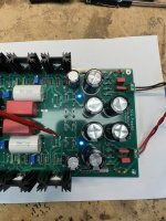
Have made good progress on the buffer. It will be different than the other headphone designs here (I hope) 🙂
Have made good progress on the buffer. It will be different than the other headphone designs here (I hope) 🙂
🙂
Keep the suspense going for a while. It is a push-pull buffer with undegenerated outputs.
Keep the suspense going for a while. It is a push-pull buffer with undegenerated outputs.
If you measured TP4 versus ground, then 104V is about right. But TP4 should be measured across R107/207. I don’t see R107/207. Are they mounted from the underside?
Btw, the guide linked in the firat post of this thread provides step-by-step instructions.
Btw, the guide linked in the firat post of this thread provides step-by-step instructions.
“connect voltmeter between TP4 and TP0 or ground. Power it up. If all goes well, you should read the sum of the zener stack at TP4. If you followed the parts list, it should be around 130V.”
So, yes I left r107/207 out…so yes vdc thought zener stack looks good. Not sure where the 130vdc comes in? I was expecting 130vdc at TP4….so you’re getting 130v across R107/207. Ok. I left those out per guide startup procedure.
So, yes I left r107/207 out…so yes vdc thought zener stack looks good. Not sure where the 130vdc comes in? I was expecting 130vdc at TP4….so you’re getting 130v across R107/207. Ok. I left those out per guide startup procedure.
Last edited:
One channel tested. Incoming AC = 120, secondary = 107vac. Zenor string of three 15 & one 75v measures 105vdc.
Vd=137.4v. Across R107 = 23mv. TP2 (Vs) to gnd = 14.5V MAX. TP1 (Vd) to gnd = 51.5v MAX. In both cases of MAX pot is turned to the click.
Network draws 51.5v/11.5r = 4.39ma.. Appears I'm a bit short of targets.
Thoughts, suggestions? Increase zener string?
Vd=137.4v. Across R107 = 23mv. TP2 (Vs) to gnd = 14.5V MAX. TP1 (Vd) to gnd = 51.5v MAX. In both cases of MAX pot is turned to the click.
Network draws 51.5v/11.5r = 4.39ma.. Appears I'm a bit short of targets.
Thoughts, suggestions? Increase zener string?
Last edited:
- Home
- Amplifiers
- Pass Labs
- Schade Common Gate (SCG) Preamp