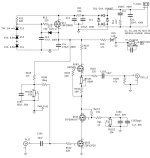
I just looked at your picture (post #991) and the schematic. The reference voltage zener string is only three zeners. The other zener, Z21, is not part of that string. So the total zener voltage is 105V. That can be measured at the cathode (black stripe) of Z22. Actual voltage will depend on parts tolerance.
TP4 looks like it is at R207, which is located at the source of the PS mosfet voltage follower. The voltage there should be the zener string voltage minus the mosfet Vgs.
TP4 looks like it is at R207, which is located at the source of the PS mosfet voltage follower. The voltage there should be the zener string voltage minus the mosfet Vgs.

Ben is right, as always. The 105Vdc reading is just fine given your zener string. Voltage across R107 is fine too, though you could raise that to 30mV.One channel tested. Incoming AC = 120, secondary = 107vac. Zenor string of three 15 & one 75v measures 105vdc.
Vd=137.4v. Across R107 = 23mv. TP2 (Vs) to gnd = 14.5V MAX. TP1 (Vd) to gnd = 51.5v MAX. In both cases of MAX pot is turned to the click.
Network draws 51.5v/11.5r = 4.39ma.. Appears I'm a bit short of targets.
Thoughts, suggestions? Increase zener string?
It is strange that TP1 to gnd is 51.5V max. There should be enough room to go higher than 51V.
You can reduce R106 to 100k and that will get you more voltage at TP2. But don't go beyond 20V. See if this change and the increase in bias current allows higher Vds across the gain FET (TP1).
The pots for the bottom and middle FET can be tricky. I have gotten into odd spots from where it takes a bit of time to get out. This is because the both the middle FET and the bottom FET have to have enough Vgs for the current to start flowing and everything to work.
Presume all other parts match the schematic for value. If not, let us know.
Attachments
Thx Ben & Ra…. All values match spot on per schemo. I’ll adjust as advised taking pot sequencing in mind. Initial pot adjust, voltages increased smoothly. Of course now I’m putting more meters on the job.
Ok…raised voltage to 25ma across R107/207. Was able to set TP2, Vs, to 19v, and TP1, Vd, to 65v. Let it cook….sinks hit 91F. As Ben said the Z-stack ( z12-14) sums to 105v….my measures were 105v left & 103.4v right. All circuit values remain per schematic. Vd of PS fet is 137v left & 136v right.
I believe it’s time to hook up & see what happens.
I believe it’s time to hook up & see what happens.
PP Output Buffer Measurements
Somebody asked about the ability of SCG to drive headphones. It can do it just fine but a buffer will give it superpowers by taking the load off the gain FET and also allow driving of really low impedance headphones, such as 45R Etys. There are some other benefits too, like being able to use a variety of TO-92 devices, including JFETs and BJTs as the gain device and lowering the distortion.
So, with that in mind, I started with a simple push-pull buffer with Fairchild MOSFETs. Following Papa's advice to avoid degeneration if possible, the buffer is just an N- and a P-channel MOSFET connected together at the source and the output taken from that point. Think F4 with a single pair of outputs and no source degeneration. The bias circuitry needs to have a bit of temperature compensation and that's all. The stock SCG output feeds the gates of the MOSFETs.
With the buffer in place, I took the opportunity to throw in the KSC1845 audio BJT, which previously sounded sterile and boring in the stock SCG. Biased at about 9 mA and TO-92 P-channel MOSFET (VP0106). Other operating points stayed about the same.
So, here are the measurements with the SCG+buffer driving 20R and 68R at about 3.0Vrms, by which point ears will be bleeding when listening to an in-ear monitor. Beyond 68R, there is no third harmonic and the 2nd just keeps going lower. Well, the measurements speak for themselves--fantastic performance and lots of drive. It sounds like it can really pound the woofers and it is definitely less sweet than the original SCG, although that can easily be changed by changing the gain device. Now I'm hearing less SCG and more of the VFET sound. The KS1845 has a little less soundstage "bloom" than the ST device, and honestly, I miss that, but it is very clean.
Driving 20R:

Driving 68R:

Somebody asked about the ability of SCG to drive headphones. It can do it just fine but a buffer will give it superpowers by taking the load off the gain FET and also allow driving of really low impedance headphones, such as 45R Etys. There are some other benefits too, like being able to use a variety of TO-92 devices, including JFETs and BJTs as the gain device and lowering the distortion.
So, with that in mind, I started with a simple push-pull buffer with Fairchild MOSFETs. Following Papa's advice to avoid degeneration if possible, the buffer is just an N- and a P-channel MOSFET connected together at the source and the output taken from that point. Think F4 with a single pair of outputs and no source degeneration. The bias circuitry needs to have a bit of temperature compensation and that's all. The stock SCG output feeds the gates of the MOSFETs.
With the buffer in place, I took the opportunity to throw in the KSC1845 audio BJT, which previously sounded sterile and boring in the stock SCG. Biased at about 9 mA and TO-92 P-channel MOSFET (VP0106). Other operating points stayed about the same.
So, here are the measurements with the SCG+buffer driving 20R and 68R at about 3.0Vrms, by which point ears will be bleeding when listening to an in-ear monitor. Beyond 68R, there is no third harmonic and the 2nd just keeps going lower. Well, the measurements speak for themselves--fantastic performance and lots of drive. It sounds like it can really pound the woofers and it is definitely less sweet than the original SCG, although that can easily be changed by changing the gain device. Now I'm hearing less SCG and more of the VFET sound. The KS1845 has a little less soundstage "bloom" than the ST device, and honestly, I miss that, but it is very clean.
Driving 20R:
Driving 68R:
I have a question for BRN. Did you happen to discover snubber values for the Triad VPS230-760?
Thanks,
Alan
Thanks,
Alan
Go here and look for your xformer:
https://www.diyaudio.com/community/threads/quasimodo-results-only.313202/
https://www.diyaudio.com/community/threads/quasimodo-results-only.313202/
I did not. I just used what was in the BOM.I have a question for BRN. Did you happen to discover snubber values for the Triad VPS230-760?
Thanks,
Alan
That baby is way overkill @ 175va. 50va is plenty.I have a question for BRN. Did you happen to discover snubber values for the Triad VPS230-760?
Thanks,
Alan
Hello,
Is it ok to use the FQP3P20 in place of the FQP12P20 for the P channel mosfet if I am using the FQP19N20 for the N channel? I have a few of them but no 12P20.
Thanks,
Alan
Is it ok to use the FQP3P20 in place of the FQP12P20 for the P channel mosfet if I am using the FQP19N20 for the N channel? I have a few of them but no 12P20.
Thanks,
Alan

Is there any magic to the 1R value of R107 / R207? The only 1R resistors I have are Dale 5% 2 watt power resistors. I have good quality 1% 10R 1/4 watt resistors if they need to be of better quality. I notice the BOM states 1R but the build guide example is 10R. Would one of the above resistors be better suited for that point in the circuit?
Thanks
Thanks
Yes, no magic there. 10R works just the same. Its sole purpose is to measure the current.
Last edited:
I finally stopped being lazy and finished up my SCG yesterday evening. I was able to find a 63 VA dual secondary 115 Volt toroidal from an old build that I had scrapped for parts. I am feeding a pair of Aleph mono-blocks. I have to put my ear directly in the horns of my 99 dB efficient speakers to hear any hiss, and It is sounding quite good after being powered up for a only few hours - a fairly big and exciting presentation. I imagine I might lower the gain at some point, as I built it mostly according to the BOM values and I don't need so much gain. However, I get plenty of control out of the stepped attenuator I used, so I am in no rush to do so.
Does anyone know if lowering the gain changes the general sound of the preamp in any noticeable manner?
Also, is there any reason not to run two sets of outputs from the preamp?
Thanks for the design and the help along the way!
Alan

Does anyone know if lowering the gain changes the general sound of the preamp in any noticeable manner?
Also, is there any reason not to run two sets of outputs from the preamp?
Thanks for the design and the help along the way!
Alan
No problem running two sets of outputs as long as the parallel load is relatively high (say > 5k). Lowering gain will likely result in less distortion and may change the sound. Try it and see what you think.
Nice build! Thanks for sharing!
Nice build! Thanks for sharing!
- Home
- Amplifiers
- Pass Labs
- Schade Common Gate (SCG) Preamp