Tubelab,
As the speaker in the BONZO DOG BAND's BIG SHOT exclaimed near the end - "Baby, you're so far ahead it's beautiful"/
Of course, he meant it very differently but the same sentiment applies to your fertile brain.
For those who wonder what I am talking about - this is one of the funniest things I have ever heard. It has made me laugh for fifty years:
I don't think that I have built a solid state audio amp since making clones of just about every one of the Tiger amps from SWTPC in the late 70's. For much of the 70's through early 90's I just cranked up the Carver / Phase Linear stuff.
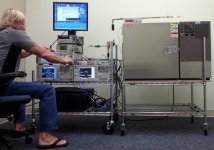
I'm known for blowing up vacuum tubes, often in a spectacular manner, but in reality I have fried far more silicon, GaAs, GaN and Sic in my life than tubes. Much of that was done on Motorola's money exploring the limits of transmitter design. This is me torture testing a 700 MHz LTE RF power amp that made over 100 watts of peak power sometime in 2010. This one survived to play again another day.
As someone else once said, "It's safe to assume that something will go boom."
Attachments

and another request to the visitors of this topic, you write that you load this preamplifier on the source follower, but if it's not a secret, can you see the schematic of this repeater? Thanks.
Mouser shows 1500 in stock
https://www.mouser.com/ProductDetai...-Atmel/DN2535N5-G?qs=GXuM9q1TrDn6RzN6idnntw==
A follower amp was posted Earlier. I have an even simpler one that I want to post in response to George’s post above. Later today.
https://www.mouser.com/ProductDetai...-Atmel/DN2535N5-G?qs=GXuM9q1TrDn6RzN6idnntw==
A follower amp was posted Earlier. I have an even simpler one that I want to post in response to George’s post above. Later today.
Thanks, is it just the shipping (as I guess) or the board shipped?I can look that up later. I would guess between $10-$15.
Check out this follower. I have been listening to it the past week. It sounds really good. Okay, it is not quite a VFET but it comes close.This thing keeps circulating around in my brain and popping up every so often, so I keep thinking about it. I even dug out an old breadboard but decided that it was too much work to make it into what I want. Now that there are some ready made boards it should be easy to build a FETSET. It would be possible, and probably easier to eliminate the OPT, but I have some decent Toroidy 600 ohm OPT's capable of 20 to 30 watts that I got for a cathode follower output stage, some 650 volt SiC J-fets, and a heat sink big enough for two boards, so I'll have to put them all together. Real tube amps have OPT's, right? I'll know more once I have the boards in hand. The question is whether to build a stereo preamp and a stereo power amp, or a pair of two stage pre / power amp boards.
It is basically a Zen amplifier with a depletion mode MOSFET (IXTH6N50D2) and instead of taking the output from the drain, you take it from the source (no voltage gain). The depletion mode simplifies the biasing, which is provided by the load (choke) plus a bit of extra resistance (0.47R) to get it in the zone. The Schade network is there but you could probably omit it and get good sound. I measured (and listened) with the Schade network and it has got a very nice second harmonic dominant profile, and it sounds like that. Sweet with a nice front to back spread, great instrument separation. Distortion is kind of high, about 0.5% at 1W, climbing to over 1% at 4W, but it stays second harmonic dominant. This is at 1.4 amps of bias. The preamp must be able to drive the 1k input. SCG does just fine with that.
Obviously, this does not use the trick of a second device, like in the SCG preamp, but it is a fine example to listen to and I'm learning a lot. With higher bias, you could get lower numbers. See Nelson's original Zen article and the Zen Redux as an example of how distortion can be lowered with higher bias.
IXTH6N50D2 follower amp schematic:
Here's a pic of the I/V curves with the 1k-47k combo (IXTH6N50D2).
Last edited:
Hi,I don't know if it was already discussed, sorry if I missed it: is it possible to build it balanced, with two boards (4 "channels")?
I can't find an info for this (maybe it's just me), so would like to ask again: is it possible to use it in balanced mode?
Many thanks in advance🙂
Isn't the 47 kOhm & 1 uF combo just making a low pass filter, considering it is referenced to the PSU?IXTH6N50D2 follower amp schematic:
Back when I was working on the modulated SMPS for transmitter efficiency improvement I met with the ON Semi sales engineer weekly along with those from several other companies who were generous with samples, notably National Semi. He gave me some of the biggest and baddest complementary pair BJT's that ON made at the time. My intention was to make a big solid state audio amp, but it never happened. I did however breadboard up a follower circuit with one of the NPN devices and drove it with a tube amp. The circuit was somewhat like yours with a 5 Hy 5 Amp choke in the emitter and a bias pot feeding the base. A variable power supply fed the collector. It did sound nice but the Mil Spec 5H @ 5A chokes (about 40 pounds each) along with about 1000 pounds of other useful iron went to the metal scrapper when I had 3 weeks' notice to get out of the house that I had lived in for 37 years and move what I wanted to keep 1200 miles. I'm going to try the OPT based setup I described first, mostly out of curiosity. If it doesn't work, who knows where I go from there.
It can drive a balanced amp using an rca to xlr cable. Just wire the negative half of the xlr to ground. Done it many times.Hi,
I can't find an info for this (maybe it's just me), so would like to ask again: is it possible to use it in balanced mode?
Many thanks in advance🙂
You could do a son of zen style implementation but that would null the second harmonic and you don’t want that.
I thought it wouldn’t do anything either but it clearly does. I measured it. It lowers overall distortion slightly but more importantly, it makes the second harmonic the dominant one, even at higher power.Isn't the 47 kOhm & 1 uF combo just making a low pass filter, considering it is referenced to the PSU?
No reason it cannot work and you are perfectly positioned for it. Very eager to see what you come up with. I just don’t have the iron to go there.Back when I was working on the modulated SMPS for transmitter efficiency improvement I met with the ON Semi sales engineer weekly along with those from several other companies who were generous with samples, notably National Semi. He gave me some of the biggest and baddest complementary pair BJT's that ON made at the time. My intention was to make a big solid state audio amp, but it never happened. I did however breadboard up a follower circuit with one of the NPN devices and drove it with a tube amp. The circuit was somewhat like yours with a 5 Hy 5 Amp choke in the emitter and a bias pot feeding the base. A variable power supply fed the collector. It did sound nice but the Mil Spec 5H @ 5A chokes (about 40 pounds each) along with about 1000 pounds of other useful iron went to the metal scrapper when I had 3 weeks' notice to get out of the house that I had lived in for 37 years and move what I wanted to keep 1200 miles. I'm going to try the OPT based setup I described first, mostly out of curiosity. If it doesn't work, who knows where I go from there.
I would use just the CT and one 120V line and wire it in parallel for both channels. That will work. Preamp draws about 70 mA, so you want at least 25VA.
Thanks @ra7 . So its 70mA for each channel or in total?
This is trafo I have and I was thinking of using 1/2 of secondary for each channel.
https://edcorusa.com/products/xpwr054-240v-100ma-ct-24v-2a-ct
This is trafo I have and I was thinking of using 1/2 of secondary for each channel.
https://edcorusa.com/products/xpwr054-240v-100ma-ct-24v-2a-ct
What are the dimensions of the new board? If you have posted this I missed it.
Should one go for the lower voltage zener string - are you settled on that ?
Thanks,
Should one go for the lower voltage zener string - are you settled on that ?
Thanks,
Last edited:
Board dimensions are 9" x 5.6".
Zener string should be between 100-130V.
With last weeks chaos and then Burning Amp, I didn't get a chance to order the boards. But I am ready now. One last thing I want to ask about is a high voltage warning. Will it be enough to simply put a warning on the PCB that high voltage is present?
Zener string should be between 100-130V.
With last weeks chaos and then Burning Amp, I didn't get a chance to order the boards. But I am ready now. One last thing I want to ask about is a high voltage warning. Will it be enough to simply put a warning on the PCB that high voltage is present?
No, 70 mA total for both channels.Thanks @ra7 . So its 70mA for each channel or in total?
This is trafo I have and I was thinking of using 1/2 of secondary for each channel.
https://edcorusa.com/products/xpwr054-240v-100ma-ct-24v-2a-ct
I have not seen the CT being shared between two bridge rectifiers. Not sure it will work. Here's the PS schematic. Wiring the CT and one 120V secondary to both sides should work fine.
- Home
- Amplifiers
- Pass Labs
- Schade Common Gate (SCG) Preamp