Ground loops in the AC power can put noise into the system. So minimizing ground loops in the power lines minimize noise in the system safety ground.
On the secondary side of the power transformer, good design and construction should minimize noise in the DC power side of the component. The connection of audio ground to safety ground is for safety, in case of an accidental short that sends voltage and current to places that they should not be. The thermistor ground lift is to partially disconnect the audio ground from the safety ground. It is low enough resistance that it can still conduct current from an accidental short (and its resistance will decrease with current), but high enough resistance that it minimizes any noise that may be in the safety ground getting to the audio ground.
So the thermistor is there to reduce any noise from the AC side from getting into the audio signal.
At least that is my understanding of the situation. 🙂

So the thermistor is there to reduce any noise from the AC side from getting into the audio signal.
That's the way I interpreted it as well. A barrier to prevent AC ground noise from coming in and messing with SCG signal ground.
In my scenario and based on my findings of yesterday...
- There is a zero-ohm path from SCG signal ground to earth ground through the DAC.
- There is a ~10 ohm path from SCG signal ground to earth ground through the SCG board and the thermistor.
I say ~10 ohm because it would take a short for the thermistor's resistance to drop to near zero ohm.
So, in normal condition, in my scenario with that DAC as it is right now, there are (at least 😉) 2 paths of different impedance between SCG signal ground and earth ground.
If I connect both the DAC and the SCG to the same power strip, these 2 paths will still be of different impedance due to the thermistor, whereas they would both be of identical impedance with a wire in place of the thermistor.
I really do not mean to beat this dead horse to death. I just hope to wrap my mind around the problem.
Thank you to everyone in this thread for all the help and patience I received! I appreciate it very much.
The signal grounds of each connected component are in parallel with each other so they are all elevated equally above earth. If each component has its own 10 ohm thermistor, then the actual resistance to earth is less than 10 ohms (10 / nComponents).I woke up with a question.
It may be a silly question. Fair warning.
I understand that plugging everything in the same power strip, surge protection device or outlet is to ensure all grounds are at the same potential, hence minimizing ground loops.
But doesn't the 10R thermistor on the way to ground on the SCG board go against that idea?
Edit:
If any component's ground is connected directly to earth, then every component's ground would also be at earth.
The signal grounds of each connected component are in parallel with each other so they are all elevated equally above earth. If each component has its own 10 ohm thermistor, then the actual resistance to earth is less than 10 ohms (10 / nComponents).
That's an excellent point! Thank you.
In my case, I think it's 10 ohm (SCG), close to zero (DAC), close to zero (power amp)...which makes the actual resistance to earth close to zero overall.
But it doesn't eliminate "multiple paths of different impedance to earth" and its potential to create ground loops...extremely small ones I guess...negligible ones.
Edit: I should have thought about your reply more before replying with this. I think what you are saying is "all components are elevated identically, therefore they see the same ground potential and there is no problem".
My thought is that with the DAC audio connected directly to AC ground, and perhaps an AC ground with noise, the noise is then in the DAC circuit and signal and continues on to the preamp, amp, and speakers.
I am suggesting that based on my system with my amplifier having a thermistor ground lift but my preamp having audio ground connected directly to chassis/safety ground, and all is quiet. So I think I have a quiet AC/safety ground.
And everything is plugged into the same wall outlet to minimize ground loops.
Last edited:
Alas, it seems common for DACs to connect signal ground to earth ground, via chassis ground.
I tested 6 DACs this morning and all of them had near 0R between the barrel of their RCA jacks and the ground pin of their IEC sockets.
I tested 6 DACs this morning and all of them had near 0R between the barrel of their RCA jacks and the ground pin of their IEC sockets.
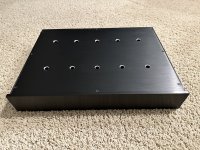
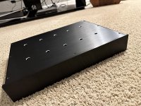
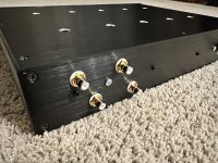
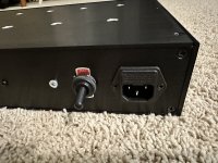
Superb! Is that a Landfall Systems chassis?
Nah, some cheap enclosure from China. But the IEC socket hole was already there, so it was great! 🙂
It's actually heftier than I expected.
Cool. Glad you hear you are enjoying it. I am close to being done with the new design, including the buffer. And not to give too much away, I just made a breakthrough yesterday. The new one is going to be fun. I’m excited.
Will post some updates next couple of days.
Excellent! The trick is always the diversity of headphones out there, across the impedance/low efficiency - high impedance/high efficiency matrix.
I have been struggling with this a lot. I have, HE6se (50R, 83.5 dB), DT-880 (600R, 96 dB), Focal Clear (55R, 104 dB)…bigger swings, more current, I always have to pick the amp wisely.
But if I could get that lush sound on 1 or all 3 of them, I would be King!
Have you tried hooking them up to the pre right now? It should drive the 600R one reasonably well.
Have you tried hooking them up to the pre right now? It should drive the 600R one reasonably well.
Yep, the DT-880 sounds great already!
I love that set on it! It sounds thin on all other amps I have.
- Home
- Amplifiers
- Pass Labs
- Schade Common Gate (SCG) Preamp