
Did you connect chassis to power gnd through the PCB? Without that the pot tends to hum in certain positions. At least it did for me. The pot body may be connected to signal ground and if it comes in contact with the chassis it could create a ground loop.
Did you connect chassis to power gnd through the PCB? Without that the pot tends to hum in certain positions. At least it did for me. The pot body may be connected to signal ground and if it comes in contact with the chassis it could create a ground loop.
Yes, I have the PCB connected to IEC ground. And so is the chassis, at the same bolt.
I also have the chassis cap and thermistor in place on the board.
In my tests right now, the pot is in an external, separate box. So, its body cannot make contact with the SCG chassis.
Okay, you might try disconnecting the power to chassis ground then and see what happens. Sometimes it is just about trying different things.
At Burning Amp, I was getting a huge amount of hum. The reason was that I had plugged the power amp in a different outlet. Putting it in the same outlet as all others got rid of it. Weird.
Lifting the power gnd to chassis connection sometimes helps.
At Burning Amp, I was getting a huge amount of hum. The reason was that I had plugged the power amp in a different outlet. Putting it in the same outlet as all others got rid of it. Weird.
Lifting the power gnd to chassis connection sometimes helps.
Last edited:
@ElArte ,
With your DMM (SCG unplugged), Check the resistance between the IEC ground pin and each RCA ground. The resistance should be the value of the thermistor or very close to it. If not, there is another path signal ground is taking bypassing the ground lift. A single point on the chassis will have Earth GND, trafo shield(if equipped), and SCG chassis GND.
Lower ohmic volume pot has less chance of introducing noise than higher value.
What is the gain of the amplifier your driving?
Attachments
View attachment 1185246
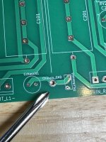
It is hard to see in this, but are the signal grounds connected to the chassis lug here or just the drains?
Just the drains.
The RCA grounds go to the board and from the board to earth ground, via the cap/thermistor pair and chassis ground.
It’s hard to fathom a loop, but the DAC is probably on the same circuit as the SCG, so who knows.
With your DMM (SCG unplugged), Check the resistance between the IEC ground pin and each RCA ground. The resistance should be the value of the thermistor or very close to it. If not, there is another path signal ground is taking bypassing the ground lift. A single point on the chassis will have Earth GND, trafo shield(if equipped), and SCG chassis GND.
Thank you,
I’ll try this in the morning.
26 dBWhat is the gain of the amplifier your driving?
I noticed a couple of things. In post #1104 (Post #1104), clip leads were connected to the chassis ground point next to the thermistor on the pcb. If these were meter grounds for voltage measurements, then the meter measurements were not at signal ground, but through the thermistor.
I noticed the shield for the input cables appeared to be chassis grounded next to the input RCA jacks, and then another wire went from this chassis ground to another chassis ground near the IEC connector. It is best to have only one ground point on the chassis. However since this ground involved only the cable shield, it probably did not create any noise.
I noticed the shield for the input cables appeared to be chassis grounded next to the input RCA jacks, and then another wire went from this chassis ground to another chassis ground near the IEC connector. It is best to have only one ground point on the chassis. However since this ground involved only the cable shield, it probably did not create any noise.
I noticed a couple of things. In post #1104 (Post #1104), clip leads were connected to the chassis ground point next to the thermistor on the pcb. If these were meter grounds for voltage measurements, then the meter measurements were not at signal ground, but through the thermistor.
That is an excellent catch indeed. I departed from TP0!
I'll have to redo that.
Thank you so much for catching that one!
I noticed the shield for the input cables appeared to be chassis grounded next to the input RCA jacks, and then another wire went from this chassis ground to another chassis ground near the IEC connector. It is best to have only one ground point on the chassis. However since this ground involved only the cable shield, it probably did not create any noise.
I agree on principle, but as you said, this additional ground point is only for the shields of the cables. And the drain wires are not connected on the other side. So, it cannot be the culprit.
The most likely culprit will be revealed in my next response to @Vunce
@ElArte ,
With your DMM (SCG unplugged), Check the resistance between the IEC ground pin and each RCA ground. The resistance should be the value of the thermistor or very close to it. If not, there is another path signal ground is taking bypassing the ground lift. A single point on the chassis will have Earth GND, trafo shield(if equipped), and SCG chassis GND.
Lower ohmic volume pot has less chance of introducing noise than higher value.
What is the gain of the amplifier your driving?
So, that was a fun little game.
I started by verifying that all RCA jacks were isolated from the chassis. They were.
Now, the set-up:
DAC -> attenuator -> SCG -> headphones (for these tests, it's easier and they are more sensitive, so it's also easier to decide if there is noise or not)
- I verified the thermistor has ~10R of resistance.
- I then measured resistance between the negative tabs of the RCA jacks and IEC ground...and resistance was 0.3R or so.
- OK, I thought. I removed all cables from the chassis...all RCA cables and the power cord. (power was not on, of course)
- Measured resistance between the negative tabs of the RCA jacks and IEC ground...and resistance was ~10R. Good.
- Reconnected all RCA cables.
- Measured resistance between the negative tabs of the RCA jacks and IEC ground...and resistance was ~10R. Good.
- Reconnected the power cord.
- Measured resistance between the negative tabs of the RCA jacks and IEC ground...and resistance was ~0.3R. Ahah!
I'm sure you know where this is going...
SCG signal ground finds a path to earth ground through the DAC, so it doesn't care about going through the SCG PCB. And that could also introduce a loop.
So, I replace the grounded DAC with a battery-powered DAC, and checked for noise...there was none.
No matter how cautious I think I am, I am always humbled by these issues.
I do not really want to float the SCG board, but it seems to be the easiest way out.
Or perhaps you could see whether you can change the dac ground so that its signal ground is not directly connected to chassis ground.
My preamp, a DIY FE 2022, has its signal ground connected directly to the chassis/safety ground and it is quiet. It is connected to my amp which has its signal ground floated by a thermistor. There is no noise from my 103dB speakers. So direct connection of signal ground to chassis ground can work. However I do not know the circumstances where it can or cannot work.
I have all of my components plugged into the same wall outlet to minimize ground loops.
So direct connection of signal ground to chassis ground can work. However I do not know the circumstances where it can or cannot work.
I have read many posts by you and I know you know a lot more than I will ever know. So, this statement is fascinating to me.
I have no hope, but I feel a little better! 😉
Fantastic troubleshooting ElArte! And thank you Ben for sharing your knowledge! Glad to hear you got no noise in one case.
Sometimes floating the signal ground helps, sometimes it doesn’t. The best place to connect signal ground to chassis is at the input. That’s hard to do with a DAC, so I’d suggest disconnecting the signal to chassis ground in the DAC. I run my Miro TDA DAC that way and it is dead quiet.
Sometimes floating the signal ground helps, sometimes it doesn’t. The best place to connect signal ground to chassis is at the input. That’s hard to do with a DAC, so I’d suggest disconnecting the signal to chassis ground in the DAC. I run my Miro TDA DAC that way and it is dead quiet.
Excellent sleuthing ElArte!!
We all have been in this frustrating game of Killing the Loop, you're definitely not alone. I actually had your same situation a while back and took the route Ben suggested. I added a ground lift to my DIY DAC and that solved it. But all situations are unique......
You're on the right path. 😉

We all have been in this frustrating game of Killing the Loop, you're definitely not alone. I actually had your same situation a while back and took the route Ben suggested. I added a ground lift to my DIY DAC and that solved it. But all situations are unique......
You're on the right path. 😉
I have read many posts by you and I know you know a lot more than I will ever know. So, this statement is fascinating to me.
I have no hope, but I feel a little better! 😉
I am an amateur diyer just like most of the members here, so there is a lot that I don't know! 🙂
Just keep an open mind and absorb knowledge, and it accumulates. I am always learning.
I have all of my components plugged into the same wall outlet to minimize ground loops.
I woke up with a question.
It may be a silly question. Fair warning.
I understand that plugging everything in the same power strip, surge protection device or outlet is to ensure all grounds are at the same potential, hence minimizing ground loops.
But doesn't the 10R thermistor on the way to ground on the SCG board go against that idea?

- Home
- Amplifiers
- Pass Labs
- Schade Common Gate (SCG) Preamp