It’s playing on my main setup and just sounding awesome 👏


Gents, reading this thread atm. So if my amp is +26dB I will have a problem with a small hiss in the speakers? Not sure how significant is this
Sound impressions? Did you hook to your sissySit?
Voxx,
It's more about the total gain which will be far to much. You will have very little usable "twist" of your volume knob, You'll go from no volume to way too loud. Look for a low gain preamp or buffer like Pass B1 or B1R2
It's more about the total gain which will be far to much. You will have very little usable "twist" of your volume knob, You'll go from no volume to way too loud. Look for a low gain preamp or buffer like Pass B1 or B1R2
Hey Voxx,
You know what this means....... You need to build another amplifier of low/no gain to enjoy SCG's magic! 🤣
You know what this means....... You need to build another amplifier of low/no gain to enjoy SCG's magic! 🤣
Looking great @manniraj!
@voxxonline, Vunce is correct about having too much gain. Edit: I see you guys found a great solution
On my speakers, which include a 110 db/W horn, I don’t hear any hiss, even with 2 SCGs in series.
@voxxonline, Vunce is correct about having too much gain. Edit: I see you guys found a great solution
On my speakers, which include a 110 db/W horn, I don’t hear any hiss, even with 2 SCGs in series.
My friend, Pano, had written a great article on gain structure:
https://www.diyaudio.com/community/threads/what-is-gain-structure.186018/
Papa’s original B1 article is also a good read on this topic.
https://www.diyaudio.com/community/threads/what-is-gain-structure.186018/
Papa’s original B1 article is also a good read on this topic.
It sounds great and I would say forward sounding compared to the HPA and Elekit. Base is just too good never heard it so tight and clean on my klipsch horns 👏Sound impressions? Did you hook to your sissySit?
Maybe I need to sell off my HPA clone now 😉
Thanks. Very helpful article. Now I know what the gain structure is and what the optimal gain level for Barry White is.
No progress occurred for nearly two weeks due to a missing Mouser order. As luck would have it, I got two of the same order from Mouser though one looked like it had been beat with a hockey stick and taped up. Some of the thermal pads were trashed, but I have plenty now and a few extra mosfets to play with. So....
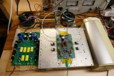
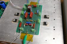
Today the breadboarded high powered SCG amp met the big heat sink shown in post #644 and got connected up to the output of the SCG board I made earlier in the thread. The big heat sink was also fed a stream of air from a portable fan. I cranked up the board on a big Sorensen power supply capable of sourcing a kilowatt and experimented with the higher powered end of the thermoelectric spectrum.
The last time I made a class A power amp I was a kid using those big TO-36 germanium transistors pulled from the back of late 50's / early 60's car radios. My "power supply" was a Lionel train transformer, some alternator diodes, and some big caps. Those transistors just started sounding good right before they blew up.
Would that happen today?
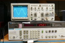
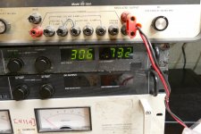
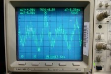
The first picture shows the setup. The beige thing on the right side of the heat sink is a portable fan on its lowest setting that blows air across the heat sink. The third picture shows a pair of overlapping sine waves on the scope from two equally matched preamps and power amps. The analyzer reads a bit over 25 watts in one channel. THD was about 1.75. The power supply for the power amp reads 306 volts at 732 mA. I am pumping 224 watts into this board and extracting 50 watts from it. At this level the output fets show about 70 degrees C on my $24 Amazon quality IR thermometer. Shutting off the drive however, makes the board eat all 224 watts pushing the mosfet temp over 90 C. With the fan running on low the heat sink is slightly warm and there is a noticeable thermal gradient from one side to the other with the coolest side touching the fan.
Measured performance is outstanding:
Power Left Ch THD Right Ch THD
100 mW 0.176% 0.166%
500 mW 0.172% 0.153%
1W 0.214% 0.181%
2W 0.268% 0.224%
5W 0.414% 0.337%
10W 0.554% 0.477%
20W 1.12% 1.00%
25W 1.77% 1.62%
30W 2.99% 3.35%
Things got hot, but nothing blew up. I'm not sure just how far I can push it though. How hot do you guys push your class A mosfet amps?
Today the breadboarded high powered SCG amp met the big heat sink shown in post #644 and got connected up to the output of the SCG board I made earlier in the thread. The big heat sink was also fed a stream of air from a portable fan. I cranked up the board on a big Sorensen power supply capable of sourcing a kilowatt and experimented with the higher powered end of the thermoelectric spectrum.
The last time I made a class A power amp I was a kid using those big TO-36 germanium transistors pulled from the back of late 50's / early 60's car radios. My "power supply" was a Lionel train transformer, some alternator diodes, and some big caps. Those transistors just started sounding good right before they blew up.
Would that happen today?
The first picture shows the setup. The beige thing on the right side of the heat sink is a portable fan on its lowest setting that blows air across the heat sink. The third picture shows a pair of overlapping sine waves on the scope from two equally matched preamps and power amps. The analyzer reads a bit over 25 watts in one channel. THD was about 1.75. The power supply for the power amp reads 306 volts at 732 mA. I am pumping 224 watts into this board and extracting 50 watts from it. At this level the output fets show about 70 degrees C on my $24 Amazon quality IR thermometer. Shutting off the drive however, makes the board eat all 224 watts pushing the mosfet temp over 90 C. With the fan running on low the heat sink is slightly warm and there is a noticeable thermal gradient from one side to the other with the coolest side touching the fan.
Measured performance is outstanding:
Power Left Ch THD Right Ch THD
100 mW 0.176% 0.166%
500 mW 0.172% 0.153%
1W 0.214% 0.181%
2W 0.268% 0.224%
5W 0.414% 0.337%
10W 0.554% 0.477%
20W 1.12% 1.00%
25W 1.77% 1.62%
30W 2.99% 3.35%
Things got hot, but nothing blew up. I'm not sure just how far I can push it though. How hot do you guys push your class A mosfet amps?
Attachments
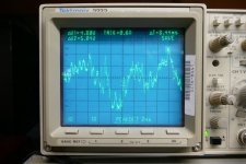
So, watching red and green numbers blink and scope traces jump is no fun, so it's time to hook up the CD player and speakers and crank it up. I played lots of different music through this thing at volume levels from mild to well into visible clipping. As with many SE vacuum tube amps you can often see some clipping on the scope before it becomes audible. Some of this is due to the magnetic storage effects in the output transformer, and some is due to the soft saturation characteristics of a vacuum tube. The same characteristic can be seen on the scope in this amp. When the top part of the trace clips, it clips hard. As the drain of the fet hits 2X the B+ voltage there is no more stored energy in the OPT and abrupt clipping occurs. As the drain of the fet is pulled toward its source the drain to source feedback resistor reduces the drive softening the landing. This can be seen in some of the scope shots here.
The first trace shows a peak to peak excursion of 50.4 volts into my "8 ohm" speakers. This is 39.8 watts, how is this possible when measured clipping occurs at just over 30 watts? Remember that this is music with multiple frequencies occurring at the same time. The large upward ramp in voltage between the two markers is at a frequency where the speakers are probably about 20 ohms.
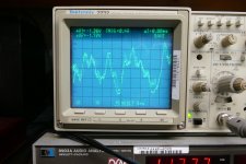
Note the rounded bottom of the clipped notes in the second picture. These are not noticeable on casual listening. If you know that they are there, you will hear it.
Here is nearly 60 volts peak to peak across my speakers. yes, it was LOUD, and clean.
With music playing the average power being produced was probably 1 watt or less. The output fets seemed to stabilize at around 90C. I shut the fan off to see what would happen and the heat sink got too hot to touch in less than a minute, so I turned it back on.
The first trace shows a peak to peak excursion of 50.4 volts into my "8 ohm" speakers. This is 39.8 watts, how is this possible when measured clipping occurs at just over 30 watts? Remember that this is music with multiple frequencies occurring at the same time. The large upward ramp in voltage between the two markers is at a frequency where the speakers are probably about 20 ohms.
Note the rounded bottom of the clipped notes in the second picture. These are not noticeable on casual listening. If you know that they are there, you will hear it.
Here is nearly 60 volts peak to peak across my speakers. yes, it was LOUD, and clean.
With music playing the average power being produced was probably 1 watt or less. The output fets seemed to stabilize at around 90C. I shut the fan off to see what would happen and the heat sink got too hot to touch in less than a minute, so I turned it back on.
Attachments
Great! Which amp are you using with it, SissySIT?It sounds great and I would say forward sounding compared to the HPA and Elekit. Base is just too good never heard it so tight and clean on my klipsch horns 👏
Maybe I need to sell off my HPA clone now 😉
Getting Barry White just right is what's it's all aboutThanks. Very helpful article. Now I know what the gain structure is and what the optimal gain level for Barry White is.

70C on the case is okay, I believe. @Zen Mod @Vunce and others may have some thoughts on it too.The power supply for the power amp reads 306 volts at 732 mA. I am pumping 224 watts into this board and extracting 50 watts from it. At this level the output fets show about 70 degrees C on my $24 Amazon quality IR thermometer. Shutting off the drive however, makes the board eat all 224 watts pushing the mosfet temp over 90 C. With the fan running on low the heat sink is slightly warm and there is a noticeable thermal gradient from one side to the other with the coolest side touching the fan.
That looks pretty much like a single-ended class A amp with a 2nd harmonic dominant profile. How does it sound?Measured performance is outstanding:
Power Left Ch THD Right Ch THD
100 mW 0.176% 0.166%
500 mW 0.172% 0.153%
1W 0.214% 0.181%
2W 0.268% 0.224%
5W 0.414% 0.337%
10W 0.554% 0.477%
20W 1.12% 1.00%
25W 1.77% 1.62%
30W 2.99% 3.35%
20-25W on TO-220, per device.Things got hot, but nothing blew up. I'm not sure just how far I can push it though. How hot do you guys push your class A mosfet amps?
40W-45W on TO-247, per device.
That is my recollection.
Good to know!So, watching red and green numbers blink and scope traces jump is no fun, so it's time to hook up the CD player and speakers and crank it up. I played lots of different music through this thing at volume levels from mild to well into visible clipping. As with many SE vacuum tube amps you can often see some clipping on the scope before it becomes audible. Some of this is due to the magnetic storage effects in the output transformer, and some is due to the soft saturation characteristics of a vacuum tube. The same characteristic can be seen on the scope in this amp. When the top part of the trace clips, it clips hard. As the drain of the fet hits 2X the B+ voltage there is no more stored energy in the OPT and abrupt clipping occurs. As the drain of the fet is pulled toward its source the drain to source feedback resistor reduces the drive softening the landing. This can be seen in some of the scope shots here.
Interesting stuff. Is symmetrical clipping a worthy goal or is it not so important? I guess it would depend on the speakers too and how loud you like to play and whether the amp will be pushed to clipping.The first trace shows a peak to peak excursion of 50.4 volts into my "8 ohm" speakers. This is 39.8 watts, how is this possible when measured clipping occurs at just over 30 watts? Remember that this is music with multiple frequencies occurring at the same time. The large upward ramp in voltage between the two markers is at a frequency where the speakers are probably about 20 ohms.
Note the rounded bottom of the clipped notes in the second picture. These are not noticeable on casual listening. If you know that they are there, you will hear it.
Good to hear! The FETSET is now aliveHere is nearly 60 volts peak to peak across my speakers. yes, it was LOUD, and clean.

Did it sound tubey?
I see the case temp hit 90C at idle and I'm dissipating over 90 watts at idle when I run the power supply at 300 volts. That gets me about 30 watts of audio at the onset of clipping. These mosfets are rated for 300 watts on a perfect heat sink made of unobtanium with an insulator make from polished unicorn skin. The data sheet quotes 180 watts of SOA at a case temp of 75C. The curves show that I can do 600 mA with 300 volts across the device at 75C, but I'm not sure exactly how to derate it to 90C. I thought about this, and how to optimize it for symmetrical clipping, but then the reality of it all slapped me in the face. Supposed I do get things to run at 90C or beyond. How am I going to deal with 225 watts of dissipation at idle. I would need a pair of those water cooling rigs from a gaming computer. I'll back things down to about 20 watts output tomorrow and reevaluate how it works.
I haven't tried to run an FFT on it yet. My old PC used just for testing amps ran XP and used an old PCI (not PCIe) audio card which died. I built a newer W10 PC but haven't set it up for testing yet.
The amp sounds great. I have listened to it for several hours today, playing a lot of the same music I used for years listening to SE tube amps with these same speakers. The FETSET has by far better dynamics, and does percussion better than a TSE or SSE, probably as good or better than the SGC feeding the vacuum tube UNSET board. Otherwise it sounds pretty much like a typical SE tube amp with lots of power. As seen in speaker testing with a scope, there is plenty of reserve voltage swing to put nearly 60 volts peak to peak across a speaker near its resonant impedance peak. I have a piece of music that tests this scenario and somewhere on my computer I have scope pictures from some of my old amps with these speakers. I need to compare them, but comparing an amp that can do 30 WPC to one that does 15 is already one sided.
These old Yamaha NS-10M Studio monitors have a 87 or 88 dB sensitivity spec so the n need a bit of power. They also reach a point where the woofer cones are at Xmax around the power level of this amp. More power does not make them louder, just more distorted. I saw that tonight when I cranked the power supply to 320 volts for a few minutes.
Yes SissySIT R3 is my main amp now a days.Great! Which amp are you using with it, SissySIT?
Also curiously after playing for couple of hrs when I switched back the preamp again in the evening the fuse blew up. I used a 0.25A rated slow blow type in the IEC socket, what is the recommended fuse here as I see reading the few posts it does not consume more than 150-200mA but not sure with the amount of capacitance on the psu side the inrush current might be their. So planning to try a 0.5-1A rated fuse.
thanks
Last edited:
TO247 case , 50W of heat, if everything else is perfect
meaning Keratherm 86/82 or Alumina pad with goop and proper sink
meaning - 55C at top of sink, no more
meaning Keratherm 86/82 or Alumina pad with goop and proper sink
meaning - 55C at top of sink, no more
- Home
- Amplifiers
- Pass Labs
- Schade Common Gate (SCG) Preamp