So it would seem that somewhere deep inside a TO247 case there is a piece of silicon screaming in pain since I have seen numbers around 85 to 90C. The sink is shiny aluminum in color, so the cheap IR thermometer says 24C no matter how hot it is. I did not know about Keratherm so I don't have any, but I do have some alumina pads and some CPU compound from PC building. I'll try that when I get a chance. I'm using some Wakefield-Vette phase change insulators that I got from Mouser, chosen for their lowest thermal resistance.
The 15 kg heat sink is upside down at the moment, so it has essentially no radiating surface when the fan is off. It stays barely warm to the touch when the fan is on, so I'm guessing about 30C. The fact that 15 kg can go from 30C to too hot to touch (about 60C) in a minute tells me that the thermal conductivity of the case to sink is pretty good.
If I choose to pursue a 30 WPC build I'll just use two big fets in parallel.

For TO247 packages using conventional aluminum finned heatsinks I've not gone much over 55W per device.
But I've pushed robust TO264 IXYS mosfets to well over 100W per device using CPU coolers and Noctua fans. No failures yet! 😆
Does that count as Fearless or Crazy??
But I've pushed robust TO264 IXYS mosfets to well over 100W per device using CPU coolers and Noctua fans. No failures yet! 😆
Does that count as Fearless or Crazy??

I am using "300 watt" IXYS IXTH6N100D2 depletion mode devices in a TO 247 package. I had a similar thought while looking at a pair of Cooler Master CPU coolers in my PC building leftovers collection. I do have some spare mosfets for when I find their limits, so I may venture down the Fearless or Crazy path. I have done dumber things.For TO247 packages using conventional aluminum finned heatsinks I've not gone much over 55W per device.
But I've pushed robust TO264 IXYS mosfets to well over 100W per device using CPU coolers and Noctua fans. No failures yet! 😆
Does that count as Fearless or Crazy??
I don't see any IXYS TO246 device rated for linear operation that can eat 600 volts or more, but I didn't look too hard. I don't need more than a few amps of current capability as the idle current will be under 500 mA.
Looks like the voltage of the IXYS's I used is no where near what you need in addition to low/no stock, as usual🙄.
747-IXFH94N30P3
747-IXTK90P20P
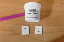
Ceramic insulators and goop👍
747-IXFH94N30P3
747-IXTK90P20P
Ceramic insulators and goop👍
That was today's experiment. Results are about the same as what I took out. I think I am asking too much from one part. If I want 30 WPC, I'll probably need two of the TO247 devices in parallel.
All of my testing has been done with the heat sink inverted so I could get to the fets while operational. Before going too far down this road, I need to flip it over and see how hot it gets in free air with no fan. I do have a bigger heat somewhere, just need to find it.
All of my testing has been done with the heat sink inverted so I could get to the fets while operational. Before going too far down this road, I need to flip it over and see how hot it gets in free air with no fan. I do have a bigger heat somewhere, just need to find it.
Attachments
I have pushed bigger parts, like the Tokin VFETs, past the 55W mark. Those computer fans are rather quiet and a good idea when trying to push things.
I am into the Keratherm thingies without the goop. Much easier to manage.
I am into the Keratherm thingies without the goop. Much easier to manage.
How do you feel about running a tube amp so hot that it melts the tube glass (envelope)? I would be terrified (being weakling and sissy 😉)! George is very much part of the FAB (fearless amp builders) gang.Does that count as Fearless or Crazy??
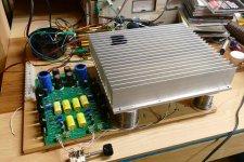
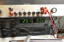
For tonight's experiment I flipped the heat sink right side up and carefully placed it on three lead filled dampers to support it. I set the power supply to 250 volts where the current started out at 530 mA and leveled off at 575 mA after everything got hot. That's 143.75 watts going into the board. Maybe 3 or 4 watts are burned in the resistors, so 140 watts gets sent to the heat sink. I blackened a few fins on the sink with a Sharpie so that the IR thermometer might read the temp. After 3 CD's had finished at a very low volume for max dissipation. I believe that the heat sink was around 55C. I could keep my hand on it for about 10 seconds. The output mosfets were around 80C though.
I have some other heat sinks stored in another building which I will try to get to tomorrow. I have two of these, but that would be a BIG amp.
I have some other heat sinks stored in another building which I will try to get to tomorrow. I have two of these, but that would be a BIG amp.
Attachments
George, be careful
with 80C on case, those 3-legged critters are ready to go poof any moment
what I wrote - 50W per puny TO247 means with perfect cooling, which is no more than 10C+ at case (ref. to heatsink near mosfet) and ( by memory) 5C to 10C more if measured at mid pin of mosfet
using contact thermometer; paid a price for using funnyguns; yes, precise enough when surface is proper, but when needing positioning precision they suck - measuring area rarely coinciding with red dot for close range, and even if you're lucky to make a point as 4eyed me, measuring area is always bigger; speaking of need to check mid pin temperature
we know that toobz are more forgiving - we see red early enough and they're gone when we are really stubborn
small buggers are far from that toughness and we can't put them in bucket of oil, unfortunately
ZM, you wrote:
“what I wrote - 50W per puny TO247 means with perfect cooling, which is no more than 10C+ at case (ref. to heatsink near mosfet) and ( by memory) 5C to 10C more if measured at mid pin of mosfet”
So, if we have 55C on sink near hand, then 10C+ near case on sink = 65C, and another 10C+ on mid pin = 75C. Does that sound right?
I know very well how quickly a solid state device can go from a semiconductor to a dead short. I might be known for melting and blowing up vacuum tubes, but truth be known, I have fried far more silicon, GaN, SiC and even some GaAs than vacuum tubes in my life. Other than those germanium transistors I melted as a kid, most of the silicon I killed was at Motorola's expense. I was a transmitter designer working on high efficiency power amps in the 5 to 150 watt range from 136 to 941 MHz range and the 1.8 to 2.6 GHz range for about 10 years.George, be careful
with 80C on case, those 3-legged critters are ready to go poof any moment
what I wrote - 50W per puny TO247 means with perfect cooling, which is no more than 10C+ at case (ref. to heatsink near mosfet) and ( by memory) 5C to 10C more if measured at mid pin of mosfet
using contact thermometer; paid a price for using funnyguns; yes, precise enough when surface is proper, but when needing positioning precision they suck - measuring area rarely coinciding with red dot for close range, and even if you're lucky to make a point as 4eyed me, measuring area is always bigger; speaking of need to check mid pin temperature
we know that toobz are more forgiving - we see red early enough and they're gone when we are really stubborn
small buggers are far from that toughness and we can't put them in bucket of oil, unfortunately
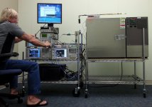
Last night's test was to find out how much power I could stuff into that heat sink before it got over 55C. I kept clicking the funnygun all over the heat sink and assumed that the highest number was closest to the correct temperature. I may try some of those Cole-Parmer Digi-Sense stick on strips to get a better handle on the actual temp rise. We used them at Motorola for basic heat sink testing. We tested our power amps inside a temperature chamber to simulate "cop radio in the trunk of a black cop car with the officers jacket thrown over the radio" kind of conditions.
Our shaker table was cool too. The old system had a huge power amp with about a dozen tubes in it driving a platter that stuff was bolted to through a 5 inch aluminum "voice coil." It did things like "5 mm or random movement on 3 axis at 15 Hz." We got a new fangled solid state unit in the 80's with preset profiles My favorite was "military off road jeep" with several power settings. Nothing known to man could survive that one on "10." Fortunately, nothing had to.
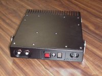
Here is one of my test radios. It puts out over 100 watts of peak LTE power at 770 MHz. The second picture shows me working hard at testing it.
Attachments

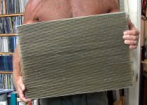
If a big heat sink is good, maybe a bigger heat sink is better........too bad I sold the really big one!
The gold anodized "bigger" heat sink is from a driver amp in a TV station. I got two at a hamfest several years ago for $10 each. I'm about to open it up to see how reusable it is.
The "really big one" was from a 2.5 KW (pulsed) RF amp out of an MRI machine. I stripped off and kept the RF stuff including some big mosfets, then sold the heat sink for more than I paid for the whole amp.
Attachments

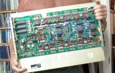
Yeah, I had no idea that I could be building a big class A solid state amp when I sold it.
It is big, and heavy but the fins are so close together that the free air flow into the spaces is likely zilch. I'm sure that the MRI machine used forced air cooling.
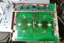
The TV station amp looks like an easy part-out, but I'll probably need to drill and tap some holes. I will find out later tonight.
It is big, and heavy but the fins are so close together that the free air flow into the spaces is likely zilch. I'm sure that the MRI machine used forced air cooling.
The TV station amp looks like an easy part-out, but I'll probably need to drill and tap some holes. I will find out later tonight.
Attachments
This preamp deserves much better chassis, so off goes BA2018 and comes in the SCG

- Home
- Amplifiers
- Pass Labs
- Schade Common Gate (SCG) Preamp