@ra7 need an input regarding the CCS procedure as I understand the below setup is just to put the DMM pins across the pins of Rlim resistor and set the CCS. Am I reading it right?
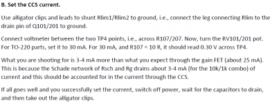
Use alligator clips and leads to shunt Rlim1/Rlim2 to ground, i.e., connect the leg connecting Rlim to the drain pin of Q101/201 to ground.
Thanks
Use alligator clips and leads to shunt Rlim1/Rlim2 to ground, i.e., connect the leg connecting Rlim to the drain pin of Q101/201 to ground.
Thanks
The regular procedure is to set ccs current first, then setup the bottom FET, then adjust the Vd of the gain FET. Otherwise, there are regions where it won’t set until the other pots are in the right zone. What’s in the guide is a sure way to get it done. But, if you know what you’re doing, just do it.
The step you mentioned is shunting the bottom end of Rlim to ground and setting the CCS current. To measure the current, you probe across Rlim or the resistor efore the CCS and after the reg. Let me know if that helps.
The step you mentioned is shunting the bottom end of Rlim to ground and setting the CCS current. To measure the current, you probe across Rlim or the resistor efore the CCS and after the reg. Let me know if that helps.

mannaraj - you just need to make something to do this.
I made mine with one of those test lead ends with the button and the small clip - no way you are going to get an alligatror clip into the center pin - I use a small alligator clip on the other end.
I am sorry I do not know the proper name for the first clip - here is a photo:

I made mine with one of those test lead ends with the button and the small clip - no way you are going to get an alligatror clip into the center pin - I use a small alligator clip on the other end.
I am sorry I do not know the proper name for the first clip - here is a photo:
Thanks Rahul, I understood the process of measuring the CCS across each of the Rlim resistors using the DMM probes but was checking with you that as I have stuffed the rest of all the remaining parts after testing the psu side should I now use the aligator clip or as Rick mentioned above clips wire to short the Rlim bottom end leg resistor to the ground like TP0?The regular procedure is to set ccs current first, then setup the bottom FET, then adjust the Vd of the gain FET. Otherwise, there are regions where it won’t set until the other pots are in the right zone. What’s in the guide is a sure way to get it done. But, if you know what you’re doing, just do it.
The step you mentioned is shunting the bottom end of Rlim to ground and setting the CCS current. To measure the current, you probe across Rlim or the resistor efore the CCS and after the reg. Let me know if that helps.
@rickmcinnis I do have those kind of thinner clips which came with my Fluke DMM kit.
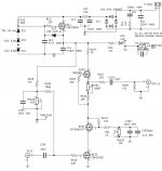
Connect to other leg of Rlim1 if you are measuring voltage across Rlim1. The arrow is pointing to the leg that connects to RV101, which comes before it. It will still work because Rlim1 is just 10 ohms or so, but you will have to measure current at R107.
Note that when you shunt the two bottom FETs, the CCS FET will carry the full 100V x 30 mA, or 3W of dissipation. So, set it quickly and turn it off. Running it for a minute or two should be fine.
Note that when you shunt the two bottom FETs, the CCS FET will carry the full 100V x 30 mA, or 3W of dissipation. So, set it quickly and turn it off. Running it for a minute or two should be fine.
Reading the initial setup instructions in post #265 I see that the suggested CCS to be around 25mA (25mV). Then the latest build guide suggested the below which is 30mA if using TO-220 FETs. So the voltage reading would be 30mV for a current setting of 30mA.

Attachments
Last edited:

My spare chassis is small to accommodate both the trafo and the amp board. So now its going to be open air preamp 😉Lookin' good Manniraj!
Music soon 😉
Just a minor observation i had a while ago when finished the pre.
Even though i had exactly the expected dc voltages in those test points, i had slightly different ac gain. I found out when i switched sony tuner to 'calibrate', which puts out mono 1kHz signal. I had slightly different ac output. Could the cheap volume pot, or more likely mosfet differences. Was easy to correct with slight tweaking.
Just in case, check ac gain.
This is one great sounding pre. Enjoy.
Good observation and good to check. AC gain is set by the Schade resistors, so it should be the same. Could be a mismatch in resistors that could exaggerate the gain difference between two channels. Always good to check. In my measurements, the two channels were dead on.
I realized that the build documentation was not linked from the first post, so here is a new post with all the relevant docs:
1. Schematic.
2. Footprints.
3. BOM.
4. Documentation/build guide.
All in the zip file. Nothing has changed since the last PCB run. Just gathering it all in one place. First post has been updated with a link to this post.
1. Schematic.
2. Footprints.
3. BOM.
4. Documentation/build guide.
All in the zip file. Nothing has changed since the last PCB run. Just gathering it all in one place. First post has been updated with a link to this post.
Attachments
I have two of the test boards, which I’ve been sending to folks for free. Just pay shipping.
I am going to order some more. Meanwhile, is there any interest in making this a store item?
I am going to order some more. Meanwhile, is there any interest in making this a store item?
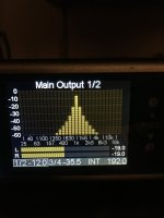
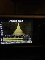
I tested this tonight and the two channels are within 0.1 db. Here are images from a loopback test from DAC->SCG->ADC.Just a minor observation i had a while ago when finished the pre.
Even though i had exactly the expected dc voltages in those test points, i had slightly different ac gain. I found out when i switched sony tuner to 'calibrate', which puts out mono 1kHz signal. I had slightly different ac output. Could the cheap volume pot, or more likely mosfet differences. Was easy to correct with slight tweaking.
Just in case, check ac gain.
This is one great sounding pre. Enjoy.
Attachments
- Home
- Amplifiers
- Pass Labs
- Schade Common Gate (SCG) Preamp