@manniraj , here's some options for P-channel MOSFETs at Mouser:
FQPF7P20
FQPF22P10
FQPF9P25
With regard to the thermistor, here's some options. The lead dia should be 0.6mm or less. I thought I chose an NTC thermistor footprint that was too small, but there are options. Really only a question of the lead fitting into the hole.
FQPF7P20
FQPF22P10
FQPF9P25
With regard to the thermistor, here's some options. The lead dia should be 0.6mm or less. I thought I chose an NTC thermistor footprint that was too small, but there are options. Really only a question of the lead fitting into the hole.
Last edited:

Thanks for this! Good to know.I have seen, tested and heard the SCG board driving an UNSET board with one large TV sweep tube per channel. It makes 20 to 25 watts per channel, sounds great and posted some good test data for a vacuum tube based amp. The test data shown was done with the tubes being run rather hard. This is OK in a Class AB push pull amp where the average power is rather low and the idle dissipation is well below the output device's spec limit. This however is a Class A Single Ended design where worst case dissipation is seen at idle and low power output, where it will spend most of its lifetime. Conventional wisdom on tube amps is to run the tubes at 70 to 80% of spec in a class A design. These tubes are rather conservatively rated at 33 to 40 watts and there is no visible glow from the guts at over 50 watts in a well constructed tube. Not all tubes are "well constructed" and testing must be performed to find good ones if they will be pushed hard.
I really like these measurements. Right up to 25W, there is almost no change in distortion. In my experience, this produces a particular type of sound where you can hear deep into the recording. There were some discussions with Ben Mah in this thread, where we discussed the SCG in comparison to a DHT preamp using the 300B tube. While the 300B tube produces superb sound, in my system it has too much sugar. As opposed to that, the SCG has sweetness but it has just enough sugar that all the details still come through. The hypothesis is that the euphonic nature of the 300B is because of increasing 2nd harmonic with level.My breadboard however looked rather sad and disconnected with two empty sockets and several dangling wires, so I decided to fix that.
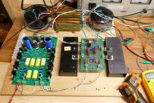
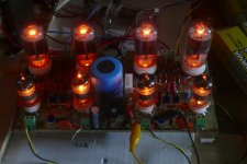
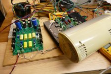
This picture shows two tubes in each board with the two tube / mosfet pairs wired in parallel. Each board is driven from one channel on the SCG board. Despite the "Nominal Power - 60W" sticker on the Toroidy OPT's, they will not do 30 watts across the audio range and saturation was seen at 20 watts below about 35 Hz. I decided to use a pair of Hammond 1628SEA's that I have owned since 2006. They are large, inefficient, and have never been used in an amplifier as long as I have owned them since I have always found something else that worked better in listening and measurement testing. The huge core requires more energy to flip all those magnetic domains back and forth, so they give up at least 10% of the applied audio power compared to the large Edcors, and probably close to 20% compared to the efficient Toroidy's that these are replacing. The Hammonds are 5K ohm and I need a lower impedance, so I am deliberately mis-wiring them to get 2500 ohms, which will waste more audio power.
The Hammonds have more stray capacitance and leakage inductance than most OPT's primarily because they are BIG. More wire, and more metal makes more inductance and capacitance. They have been consistently marginal in HF frequency response with an upper 3dB point in the 18 to 25 KHz range in a typical SE tube amp design like my SSE. The vacuum tube based UNSET changed that with frequency response from about 20 Hz to mid 30 KHz due to the low driving impedance it presents to the transformer. This reduces the "Q" of the resonant notch formed by the stray capacitance and leakage inductance. Listening tests with an UNSET board driving these transformers were very positive.
Running Two UNSET circuits in parallel further reduces the driving impedance to the OPT and allows for a more conservative operating point. I fired the breadboard amp up and set each tube for 35 watts of dissipation. The amp began to clip around 30 watts and hit 5.5% THD at 35 watts. I believe that this would be a 40 watt amp with a more efficient OPT. The 3 dB frequency response at 20 watts of audio output was 16 Hz to 45 KHz, a number previously unseen with these transformers. THD vs Power at 1 KHz is below. Both channels were nearly identical. It took 1.05 Vrms to drive the amp to 20 watts of output.
0.1 W 0.39% limited by 60 Hz hum
0.5 W 0.31% also limited by 60 Hz hum
1.0 W 0.30%
2.0 W 0.32%
5.0 W 0.40%
10 W 0.46%
15 W 0.48%
20 W 0.57%
25 W 0.61%
30 W 1.76%
35 W 5.51%
That sucks! But great to read through your troubleshooting process.I decided to hook up the CD player and speakers, but that's where everything went wrong leaving me with smoke, unanswered questions, and dead parts.
Everything was wired up, the tube heaters were pre-heated, and I brought up the power supply that feeds the SCG board first. When I switched on the power supply that feeds the output tubes the 20 amp breaker in the panel tripped. This should not happen since there is a 15 amp breaker on my workbench, and no other load was on the 20 amp breaker. This had to be a GCFI based trip. I began to unplug all of the test equipment and plug things back in one at a time trying to find the leakage path. Both of my 600+ volt power supplies were originally sold as metal scrap and had the big HP6448B had been wet before and was a bit rusty inside, but has been reliable for 15 years, and was not being used at the time. It also has both sides of the power line input switched. The 555 Volt Fluke is dead and also not used or plugged in. The 400 volt Knight Kit has been rebuilt and is powering the SCG board.
I suspected the Sorensen switcher since it was also a rescue from scrap and the second picture shows what it looked like when I got it. I decided to disconnect it and swap it with the big HP6448B. Unfortunately, I accidentally swapped two banana plugs and fed 450 volts at up to 1.7 amps into the SCG board and the vacuum tube screen grids. When I hit the power switch the fire gods danced and the smoke monster descended on all 3 boards. I had a small fan running to keep things cool so I could not see what smoked, I watched the current meter as I hit the on switch and immediately killed power when I saw it pass 1 Amp. I don't see any obvious blown stuff, but I haven't looked very carefully. I'm still looking for the reason the breaker pops.
This morning the breaker was still popping whenever I turned on the switching power supply and any other piece of test equipment, but it also popped when I turned on the scope and audio analyzer with the power supply off. I decided to move the stack of equipment but found nothing and the problem vanished. Things that "fix themselves" often unfix themselves at the most inopportune moment. I'm going to take that supply apart for a better look. While the bench is a mess, I need to look inside my Fluke 407D. It was yet another metal scrap salvage that I got on Ebay for $25 plus $45 shipping over 20 years ago. It worked when I got it and other than some loose pots, has worked fine until a couple months ago. It was built around 1970 and still contains all of its original parts. It probably needs a total rebuild.
Huh! I'm perplexed by the input FET getting fried. I am yet to lose one and I am hot swapping from the DAC all the time. Maybe the CD player doesn't like hot swapping.I ripped my workbench apart in an attempt to find the cause of the GCFI trips but failed to find the cause. I cleaned up the ratsnest of wiring behind the equipment and took the Fluke 407D apart to see if there was an obvious clue to its fault but found nothing obvious. I think I'll replace all of the tubes and try it again as they are all 50 years old, and I have seriously abused this thing.
I put back the power supplies and began to troubleshoot the dead amp expecting the worst. I powered up the SCG board by itself and found it to be drawing almost 200 mA instead of 60. One channel however, worked just fine and the other was dead. Voltage readings revealed a fried input fet, so I replaced it. This brought the other channel back, but the current was still high, but not as bad as before. I soon realized that one of the big blue electrolytics was getting warm and there were signs that it had vented. Oddly the characteristic stink of a vented electrolytic did not occur, or I would have looked for that first. The 100 ohm resistor that feeds that cap was a bit darker than its brother in the other channel.
Yeah, that stink of a vented cap is unmistakable.
Yeah, 500W is a lot of heat. Even 300W is a lot. The FETSET might be more efficient because of the absence of heaters.I hooked everything else back up and the amp works. After about 15 minutes of testing the blue cap was quite warm but the current kept creeping downward so I connected up the CD player and the speakers. I have never heard sound like that come from these big transformers, and even with 87 dB speakers it goes quite loud. Percussion is very dynamic, and everything sounds quite real. Everything has its drawbacks, and to some this amp's worst characteristic is the 300 watts or heat it puts into the room at idle. Almost 30 years ago I built a 30 WPC SE tube amp using 211 or 845 transmitting triodes on 1050 volts. It sounded quite nice but didn't have anything close to the dynamics that this amp has. It also put over 500 watts into the room. That didn't work in my 100 square foot room in Florida, so the amp never got much play time, and it still sits on a shelf in the corner unused. It's currently 33 degrees outside, a few extra watts of heat in the basement is a good thing.
That 211/845 amp seems very cool and very scary at the same time 🙂
Right now, the heat pump is grinding away putting several kilowatts of heat into the house and it's 64 degrees in the basement. A few hundred more would be welcome.Yeah, 500W is a lot of heat. Even 300W is a lot. The FETSET might be more efficient because of the absence of heaters.
I thought about that statement and realized a few errors in my comparison. The numbers are correct, but the two amps are not even close to being the same thing.
The heater power in the output stages is nearly identical. The SCG / UNSET has 4 tubes with 26 volt 600 mA heaters for a total of 62.4 watts. The 211 / 845 amp has two tubes with 10 volt 3.25 Amp heaters for a total of 65 watts.
I made the heat generation statement for the SCG / UNSET setup simply by reading the meters on the power supplies adding the power used plus the 62 watts for the heaters which is supplied by the silver Meanwell unit on the left side of the picture. This is a correct measurement for the amp itself. One of the bench power supplies is a switcher with an unknown, but probably decent efficiency, bur the Knight Kit unit running the SCG board is full of vacuum tubes including 4 X 6L6GC.
The 211 / 845 amp has its power supply on the smaller of the two chassis. It uses a vacuum tube based linear power supply which was included in the heat generation numbers. It also uses a 45 based TSE board for the driver that consumes about 11 watts for its heaters, and a power supply with 3 5AR4 rectifiers for about 15 watts more of heater power.
The output stage in the 211 / 845 amp could run either tube. It contained a mosfet driving the grid for class A2 operation. I ran old tubes at 70 mA and about 1070 volts for a power input of about 75 watts per channel. This produced about 25 WPC of audio. I got several new Chinese tubes back when they were about $30 each, so I didn't mind bending the spec a bit going over 100 mA which dropped the plate voltage to about 1050 for about 105 watts of input which yielded 30 WPC of output. Going to 120 mA actually reduced the power output because the B+ voltage sagged further. It did however improved the bass due to the higher damping factor.
Last night's listening session had 105 mA flowing through each tube / mosfet combo on 504 volts of B+ for an identical 105 watts of input. I could however get about 34 watts at 5% THD which was the measurement criteria I used to use when the 211 / 845 amp was built and tested. The Hammond OPT used in the SCG / UNSET tests is less efficient than the transformer in the 211 / 845 amp. Increasing the current further in the output tubes did very little if anything for the sound quality but did gain a couple more watts in output power. At this point the driver and output sections are both hitting the clipping wall. I may swap in a higher voltage zener in the SCG board and test again, but I won't be home today, so maybe tomorrow.
 Woohoo! Can’t wait!
The initial experiments that led to the common grid or common gate topology found in the SCG and UNSET started in 2017 as an idea for a way to make low buck vacuum tube guitar amps. There were a few successes, but far more failures including a pair of exploding vacuum tubes.
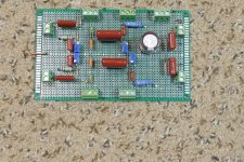
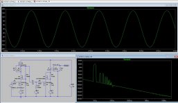
The first successful test board is seen in the first picture. The setup is my typical breadboarded 2 channel tube amp with the output board on the right replaced with a perfboard experiment. The mosfets are mounted on a black heatsink underneath the perfboard. The "Schade" resistors are in the spring clips on either side since they were constantly being changed. White and yellow clip leads put meters across 1 ohm resistors in series with the P-fet drain.
The first successful amp with this topology is seen in the second picture. All the tubes used here were on the $1 list, so 70 WPC flowed from $8 worth of tubes.
Several discussions about low cost guitar amps occurred in, or spun off from the Hundred Buck Amp Challenge thread:
https://www.diyaudio.com/community/threads/the-hundred-buck-amp-challenge.190738/
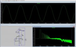
In one of these I had mentioned that I had stuck a pair of LND150 mosfets into the 12AX7 (vacuum tube twin triode) socket in a guitar amp with no other changes and it worked very well. This experiment and discussions led to some simulation and a redesign of the 4 tube guitar amp I build for that challenge. It now contains 4 tubes and two LND150's, and remains the only guitar amp I use regularly.
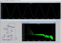
The sim in the first picture may look somewhat familiar. It was intended for driver applications and can produce 300 volts peak to peak with about 0.5% THD in real world bench testing.
I also tested a similar design with a j-fet for the gain device. It also had decent performance but could only be run at low voltages due to the j-fets breakdown voltage rating.
I simulated several two stage circuits in an attempt to get from line level to speaker level, assuming a single ended output stage with an output transformer like those seen in a typical tube amp. There were all tube sims, sims with a tube and a fet, and a couple of all fet sims. I went in the all tube direction first and created the UNSET design. The story is here if anyone is interested:
https://www.diyaudio.com/community/threads/unset-is-coming.340856/
All of those experiments left dozens of LT spice simulations, and some partially finished test boards behind. There were some two stage FETSET sims and a partially finished breadboard that went nowhere until I found this thread. I grabbed a simulation that poorly worked, but showed promise and played the "Pick new mosfet" game until it began to work, then tweaked from there. A few hours later and I had a sim for an audio power amp (5th picture).
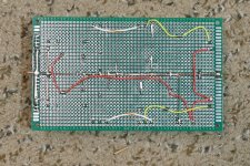
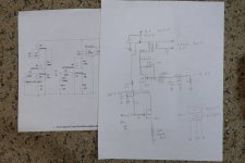
I distilled the important info from the sim and created a schematic for an output stage that could be built with physical parts the old fashioned way, with pencil and paper and several boxes full pf parts. It soon became obvious that my old test board wouldn't work, so I created a new one. 6th and 7th pictures.
The test board worked perfectly, but mosfet heat killed the fun before I could find the limits. The sim revealed that I should be able to get 35 WPC with under 1% THD on 300 volts of B+ with 350 mA of idle current into my 600 ohm OPT's. This is 105 watts of dissipation per channel, with about 85 watts of that in the gain device.
In order to extend the test levels, I resorted to "cold air induction." The meter at the end of the board blocks the air exit forcing it out through the heat sinks. This gave me a few very short test periods where I did see over 20 watts at under 2% THD on each channel. During a 30 second or so test the mosfets hit 80C while the heat sinks barely got over 30C. I haven't built anything with TO-247 devices in ages, so my 20+ year old thermal pads that were pulled from another heat sink are probably useless.
This design sees up to 2X the B+ voltage on the drain of the gain fet. The heat sink needs to be grounded to avoid a shocking experience, so I ordered a bunch of different kinds of thermal "solutions" from Mouser yesterday.
Those heat sinks are not big enough to dissipate 200 watts, so I'll need to drill and tap proper holes in the big one seen in post #644. I have two of them if one isn't enough. My drill press is in the garage, so that operation will be delayed until the sideways blowing rain / snow slows down a bit, maybe Sunday. Another possibility is the use of some of the CPU coolers that I have accumulated in 40 years of PC building.
The first successful test board is seen in the first picture. The setup is my typical breadboarded 2 channel tube amp with the output board on the right replaced with a perfboard experiment. The mosfets are mounted on a black heatsink underneath the perfboard. The "Schade" resistors are in the spring clips on either side since they were constantly being changed. White and yellow clip leads put meters across 1 ohm resistors in series with the P-fet drain.
The first successful amp with this topology is seen in the second picture. All the tubes used here were on the $1 list, so 70 WPC flowed from $8 worth of tubes.
Several discussions about low cost guitar amps occurred in, or spun off from the Hundred Buck Amp Challenge thread:
https://www.diyaudio.com/community/threads/the-hundred-buck-amp-challenge.190738/
In one of these I had mentioned that I had stuck a pair of LND150 mosfets into the 12AX7 (vacuum tube twin triode) socket in a guitar amp with no other changes and it worked very well. This experiment and discussions led to some simulation and a redesign of the 4 tube guitar amp I build for that challenge. It now contains 4 tubes and two LND150's, and remains the only guitar amp I use regularly.
The sim in the first picture may look somewhat familiar. It was intended for driver applications and can produce 300 volts peak to peak with about 0.5% THD in real world bench testing.
I also tested a similar design with a j-fet for the gain device. It also had decent performance but could only be run at low voltages due to the j-fets breakdown voltage rating.
I simulated several two stage circuits in an attempt to get from line level to speaker level, assuming a single ended output stage with an output transformer like those seen in a typical tube amp. There were all tube sims, sims with a tube and a fet, and a couple of all fet sims. I went in the all tube direction first and created the UNSET design. The story is here if anyone is interested:
https://www.diyaudio.com/community/threads/unset-is-coming.340856/
All of those experiments left dozens of LT spice simulations, and some partially finished test boards behind. There were some two stage FETSET sims and a partially finished breadboard that went nowhere until I found this thread. I grabbed a simulation that poorly worked, but showed promise and played the "Pick new mosfet" game until it began to work, then tweaked from there. A few hours later and I had a sim for an audio power amp (5th picture).
I distilled the important info from the sim and created a schematic for an output stage that could be built with physical parts the old fashioned way, with pencil and paper and several boxes full pf parts. It soon became obvious that my old test board wouldn't work, so I created a new one. 6th and 7th pictures.
The test board worked perfectly, but mosfet heat killed the fun before I could find the limits. The sim revealed that I should be able to get 35 WPC with under 1% THD on 300 volts of B+ with 350 mA of idle current into my 600 ohm OPT's. This is 105 watts of dissipation per channel, with about 85 watts of that in the gain device.
In order to extend the test levels, I resorted to "cold air induction." The meter at the end of the board blocks the air exit forcing it out through the heat sinks. This gave me a few very short test periods where I did see over 20 watts at under 2% THD on each channel. During a 30 second or so test the mosfets hit 80C while the heat sinks barely got over 30C. I haven't built anything with TO-247 devices in ages, so my 20+ year old thermal pads that were pulled from another heat sink are probably useless.
This design sees up to 2X the B+ voltage on the drain of the gain fet. The heat sink needs to be grounded to avoid a shocking experience, so I ordered a bunch of different kinds of thermal "solutions" from Mouser yesterday.
Those heat sinks are not big enough to dissipate 200 watts, so I'll need to drill and tap proper holes in the big one seen in post #644. I have two of them if one isn't enough. My drill press is in the garage, so that operation will be delayed until the sideways blowing rain / snow slows down a bit, maybe Sunday. Another possibility is the use of some of the CPU coolers that I have accumulated in 40 years of PC building.
Attachments
-
 P4000916.JPG723.5 KB · Views: 212
 -
 P4000913.JPG664.4 KB · Views: 164
 -
 FETSET_2STAGE.jpg195.1 KB · Views: 157
 -
 J-FETSET.jpg231.6 KB · Views: 165
 -
 FETSET-LND150.jpg208.5 KB · Views: 167
 -
 P1850371.JPG324.6 KB · Views: 180
 -
 P1000889.JPG606.6 KB · Views: 173
 -
 P4000902.JPG477.5 KB · Views: 231
 -
 P4000910.JPG281.3 KB · Views: 232
Heat is a problem with this single-ended topology. The trafo or choke as a load helps with improving efficiency. But 300V and 350 mA is a lot. Also, it must a huge transformer.
The LND150 sim is amazing. Gain of 40X? Superb linearity. Maybe it can be a preamp in its own right with a buffer on the output. I tried the LND150 in the current preamp. When driving the gates of SITs, I found you needed at least 8 mA of drive. The LND150 wasn’t cutting it. But maybe with a buffer.
Love the hand drawn schematic. I recently read in one of Nelson’s early Zen articles that a lower impedance feedback network provides more current for charging the gate capacitance of the MOSFET. I see high impedances in that last schematic. Have you tried with lower impedance? I did notice a difference between 100k/10k and 10k/1k preferring the latter. The bigger mosfets want even more current, I presume.
Hope you get better weather soon. It is rain rain rain here in northern CA.
What is that giant can in the third from last picture?
Heat is a problem in all SE topologies since they must run in class A. About 15 years ago I used some RF power amp technology for cell towers that I was working on at Motorola to create a high efficiency SE class A vacuum tube amp which was entered into a Circuit Cellar / Microchip design contest where it won a prize which resulted in a published magazine article. For this to work the output stage must be a follower or other buffer topology with a very high PSRR. A cathode or source follower would be ideal. I think I have experimented with just about every possible way to "missapply" vacuum tubes, but I have always wanted to revisit the tech used in that article. Now technology has advanced enough that all this could be done in a powerful Arduino compatible like a Teensy 4.1. The output stage would be a simple cathode or source follower, which is why most of my simulations have focused on generating a large drive voltage at enough current to drive the capacitance of a follower without slew rate issues. A vacuum tube has the drive capacitance advantage, but loses the efficiency race due to its heater power. Both will be tested. I'm including the magazine article from 2009 in case anyone is interested.Heat is a problem with this single-ended topology. The trafo or choke as a load helps with improving efficiency. But 300V and 350 mA is a lot. Also, it must a huge transformer.
The LND150 sim is amazing. Gain of 40X? Superb linearity. Maybe it can be a preamp in its own right with a buffer on the output. I tried the LND150 in the current preamp. When driving the gates of SITs, I found you needed at least 8 mA of drive. The LND150 wasn’t cutting it. But maybe with a buffer.
Love the hand drawn schematic. I recently read in one of Nelson’s early Zen articles that a lower impedance feedback network provides more current for charging the gate capacitance of the MOSFET. I see high impedances in that last schematic. Have you tried with lower impedance? I did notice a difference between 100k/10k and 10k/1k preferring the latter. The bigger mosfets want even more current, I presume.
Hope you get better weather soon. It is rain rain rain here in northern CA.
What is that giant can in the third from last picture?
When I dug up the old sim that I used in my last post both stages used the same VP0106 - LND150 - DN2540 lineup. This made 300 volts peak to peak with low THD, but couldn't drive anything. I simply played the "pick a new mosfet" roulette wheel until I got something that worked, then built it.
I plan to mess around with the feedback resistors once I have the amp thermally stable. It's far easier to parallel resistors across existing parts that are too high in value that it is to change them, so when I'm building a proto, I always start too high on resistor values, and too low on capacitors. I made the mosfets easily swappable here too since I have lots of them to try for power output and voltage output test conditions. I also used 450 volt or higher capacitors so I can test this thing up to 450 volts.
The large metal can is a 100 uF 370 VAC (good for over 500 VDC) motor RUN cap in parallel with my 50 year old Fluke 407D power supply. Motor RUN caps like found in an air conditioner are low ESR polypropylene capacitors which can provide a quick pulse of current to feed musical transients like drum hits. Builders of my amplifiers have been using these in parallel with the on board electrolytic for years. Most users including myself find increased dynamics especially on percussive music. Note that motor RUN cape are designed to run directly in series with the AC line and a big motor. They are designed to handle AMPS of current continuously forever with low loss. A motor START cap is usually a cheap electrolytic which must NOT be used in a tube amp, as it is designed for short term duty and could leak, vent, or even explode if left across a power source continuously.
The weather is definitely weird this winter. The "atmospheric river" that trashed southern California and dropped tornados across the south gave us two days of rain and now two days of snow. It looks like two more or these things are going to work their way across the country.
Attachments
Thanks for the article! I'll take a look. I do think tubes have a huge advantage in the drive capacitance parameter and I could go as far as to say that this feature is one of the reasons for the tube sound (my thinking given my modest experience with everything). MOSFETs suck in this regard and many times the bad sound (harsh, bright, brittle) could be attributed to not enough drive current. I have certainly tried it in the SCG and can attest to that the bad sound when there is not enough current feeding that capacitance, both for the gain FET's drain and when the preamp as a whole doesn't have enough current to drive the next stage.Heat is a problem in all SE topologies since they must run in class A. About 15 years ago I used some RF power amp technology for cell towers that I was working on at Motorola to create a high efficiency SE class A vacuum tube amp which was entered into a Circuit Cellar / Microchip design contest where it won a prize which resulted in a published magazine article. For this to work the output stage must be a follower or other buffer topology with a very high PSRR. A cathode or source follower would be ideal. I think I have experimented with just about every possible way to "missapply" vacuum tubes, but I have always wanted to revisit the tech used in that article. Now technology has advanced enough that all this could be done in a powerful Arduino compatible like a Teensy 4.1. The output stage would be a simple cathode or source follower, which is why most of my simulations have focused on generating a large drive voltage at enough current to drive the capacitance of a follower without slew rate issues. A vacuum tube has the drive capacitance advantage, but loses the efficiency race due to its heater power. Both will be tested. I'm including the magazine article from 2009 in case anyone is interested.
Thank for this! I want to try this out in the bypass position for the gain FET. It might be too big to fit, we shall see.The large metal can is a 100 uF 370 VAC (good for over 500 VDC) motor RUN cap in parallel with my 50 year old Fluke 407D power supply. Motor RUN caps like found in an air conditioner are low ESR polypropylene capacitors which can provide a quick pulse of current to feed musical transients like drum hits. Builders of my amplifiers have been using these in parallel with the on board electrolytic for years. Most users including myself find increased dynamics especially on percussive music. Note that motor RUN cape are designed to run directly in series with the AC line and a big motor. They are designed to handle AMPS of current continuously forever with low loss. A motor START cap is usually a cheap electrolytic which must NOT be used in a tube amp, as it is designed for short term duty and could leak, vent, or even explode if left across a power source continuously.
Sorry I have been late in replying to several posts. Life has gotten underway since the new year but the full time job and school schedules, plus sicknesses and the rain. It is all fun all the time 🙂. Hope to get to replies in a day or two at most.
Have you tried a BJT in the gain device position? I stuck a few of them in recently, they worked AND performed admirably. I didn't listen to it long enough to formulate an strong opinion but they sounded damn good in the short while that I listened. The ones I tried were BC550B, ZTX450, and MPSA something. Those were the ones I had on hand and BC550B at about 12 mA was the best of the three. BJTs may have the advantage in input capacitance.When I dug up the old sim that I used in my last post both stages used the same VP0106 - LND150 - DN2540 lineup. This made 300 volts peak to peak with low THD, but couldn't drive anything. I simply played the "pick a new mosfet" roulette wheel until I got something that worked, then built it.
Yesterday, I travelled to Auburn, which is about an hour's drive from Davis to meet Mark W. and Jam S. Jam is a noted designer and ex-Pass Labs. I showed him this circuit and he immediately asked if I had tried BJTs. So, I am going to give it a thorough listen with BJTs. There was some good conversation with Mark and Jam and some listening to tunes. A fun visit. I feel like as audiophiles (yes, declare that you are one!) we need to get together more often because it is fun and it helps recalibrate your brain after listening to a different system. I try to do it every chance I get. I remember about 15 years ago, I heard Pano's VOTT-based system and got hooked on horns. These experiences have been vital in understanding what is achievable and how things should sound. Listening to live music is also a big part of it.
Just read through the article. Simply phenomenal. This would be a really cool challenge using an Arduino-based system, as you suggest above. Thanks for sharing!Heat is a problem in all SE topologies since they must run in class A. About 15 years ago I used some RF power amp technology for cell towers that I was working on at Motorola to create a high efficiency SE class A vacuum tube amp which was entered into a Circuit Cellar / Microchip design contest where it won a prize which resulted in a published magazine article. For this to work the output stage must be a follower or other buffer topology with a very high PSRR. A cathode or source follower would be ideal. I think I have experimented with just about every possible way to "missapply" vacuum tubes, but I have always wanted to revisit the tech used in that article. Now technology has advanced enough that all this could be done in a powerful Arduino compatible like a Teensy 4.1. The output stage would be a simple cathode or source follower, which is why most of my simulations have focused on generating a large drive voltage at enough current to drive the capacitance of a follower without slew rate issues. A vacuum tube has the drive capacitance advantage, but loses the efficiency race due to its heater power. Both will be tested. I'm including the magazine article from 2009 in case anyone is interested.
I believe Bill Waslo's Class A design in LA used a modulated supply:
https://linearaudio.net/article-detail/2272
And I remember Nelson also modulated the supply in ZV3:
https://www.firstwatt.com/pdf/art_zv3.pdf
That is the PNP counterpart to my suggestion. While we are discussing alternative components, is there an alternative for the Depletion MOSFET?Will add that to the list, Sam! Also want to try Nelson's device of choice for the 2022 FE.
I never thought to try them. I think I have some MJE350's around here somewhere, but they have to be at least 25 years old since they wear the Motorola brand. I probably have some other parts that will eat 100+ volts too.Have you tried a BJT in the gain device position?
I currently have a IXTP6N100D2 TO-247 depletion mode FET with an SOA rating of 600 mA at 300 volts for my gain device in the power stage. If I blow that up, there isn't much else to try that's in my budget. I haven't tried the SiC FETS yet though. Need better thermal management before going much further.
The DN2540N5, IXTP1R6N100D2, IXTP08N100D2, IXTP3N100D2, IXTP01N100D, IXCP10M45S, and IXCP10M90S will all work. The last three are rated for only 100 mA, so don't go beyond 100 mA with them.While we are discussing alternative components, is there an alternative for the Depletion MOSFET?
For NPN BJT, KSC/2SC 1845 should be better than BC550B.
- Home
- Amplifiers
- Pass Labs
- Schade Common Gate (SCG) Preamp