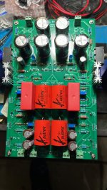
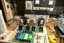
I put this together with parts that I had in my stash. The only part I purchased for this board was the gain mosfet which I got back when it was mentioned that they were getting hard to find. I didn't go by the parts list, I just looked at the schematic and picked the best fit from what I had. Nothing except for most of the small resistors is the correct part. I fired up the power supply from a bench supply and tested it before installing any other parts to avoid fried stuff if the supply is way off. One channel has 118 volts and the other has 121, and it remains constant with a raw supply voltage from 130 to 180 volts.
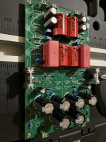
This is as nice as it will ever look, because once I start messing with it ugliness happens.
This is as nice as it will ever look, because once I start messing with it ugliness happens.
Attachments

Last edited:

Looking great, George!I put this together with parts that I had in my stash. The only part I purchased for this board was the gain mosfet which I got back when it was mentioned that they were getting hard to find. I didn't go by the parts list, I just looked at the schematic and picked the best fit from what I had. Nothing except for most of the small resistors is the correct part. I fired up the power supply from a bench supply and tested it before installing any other parts to avoid fried stuff if the supply is way off. One channel has 118 volts and the other has 121, and it remains constant with a raw supply voltage from 130 to 180 volts.
This is as nice as it will ever look, because once I start messing with it ugliness happens.
 Good to know that the regs are working.
Please let me know if you have any suggestions on the PCB, layout, etc. I've already learned so much from you!
Can't wait for the ugliness!!!

Looking good!Almost done waiting for the remaining mosfets arrival.
I powered the board up this morning to find my first dead part. I did all the current and voltage adjustments on the left channel, and all went well. The current adjustment on the right channel went well but the voltage at TP1 wouldn't stay set, it just wandered. A little poking around with a voltmeter revealed that Z22 couldn't remember what its breakdown voltage was. Eventually it decided to become completely open. I have a good collection of zener diodes that came from a lot of surplus parts from 1974, so finding one bad diode out of 8 isn't a big surprise. Another from the same bag worked fine. I have two 53 volt, and one 18 volt in each string, and one of the 53's died.
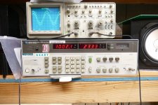
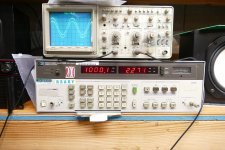
I applied a signal and cranked up the drive to find clipping. It's just over 30 V RMS. THD is .23% at 30 V RMS. Both channels are identical. The frequency response at 30 V RMS can not be measured with my equipment, since the -3dB points are below 20 Hz and above 100 KHz which is the range of the old HP8903A. The response is down 0.25 dB at 20 Hz and at 33.1KHz. THD at 30 volts and 20 Hz remains .23% but rises to almost 2% when trying to drive 30 V at 20 KHz into the scope and audio analyzer plus a mess of random wiring.
I plan to use this board to drive something BIGGER, but full power at 20 KHz is not a concern for several reasons. I did not use the correct part for the P channel fet so this may be part of the problem. It could also be a crappy cap. Those yellow REL-Caps are at least 30 years old too.
I will be playing musical parts and exploring higher voltage operation in a quest for more output voltage swing, but as I tell others here on diyAudio, build it per instructions first, and make sure it works, before messing with it, whatever it is. Then make ONE change at a time and evaluate it.
Attachments
😆I powered the board up this morning to find my first A little poking around with a voltmeter revealed that Z22 couldn't remember what its breakdown voltage was. Eventually it decided to become completely open.
Thank you so much for testing. Looks about right. I could never drive it to clipping given the soundcard’s max output but at some point, I recall doing 25 Vrms without clipping, which is plenty for the SS amps we deal with here.I applied a signal and cranked up the drive to find clipping. It's just over 30 V RMS. THD is .23% at 30 V RMS. Both channels are identical. The frequency response at 30 V RMS can not be measured with my equipment, since the -3dB points are below 20 Hz and above 100 KHz which is the range of the old HP8903A. The response is down 0.25 dB at 20 Hz and at 33.1KHz. THD at 30 volts and 20 Hz remains .23% but rises to almost 2% when trying to drive 30 V at 20 KHz into the scope and audio analyzer plus a mess of random wiring.
Very good adviceI will be playing musical parts and exploring higher voltage operation in a quest for more output voltage swing, but as I tell others here on diyAudio, build it per instructions first, and make sure it works, before messing with it, whatever it is. Then make ONE change at a time and evaluate it.

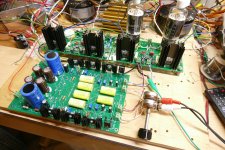
Anyone who knows me can guess what my next experiment would be. There was a picture in post #732 that showed a pair of UNSET vacuum tube output boards that had been squeezed for over 500 watts in push pull. These boards can be configured for SE where they will make up to 30 watts per tube, given a suitable driver board. Well, we now have a new driver board, so the two must meet.
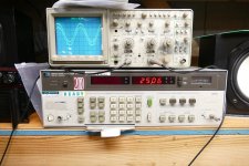
The result is a SE stereo hybrid amp that makes 25 WPC. THD is 2.3% at 25 watts and 0.35% at 1 watt. It however needs 2.7 volts RMS of drive to get to 25 watts. Now the "messy stuff" begins.
I got to stick some speakers on this thing.......
There is still the box full of big fets to play with. I think I'll go back to my breadboard for those experiments and save the second SCG board for a possible two stage driver setup, or maybe even a headphone amp.
Attachments

Good question! I need to look at KiCAD because the footprint was from KiCAD--think I picked one that was too small. Will get back to you tomorrow. On the PCB, I saw it was too small and so I just connected a 10R, 0.25W resistor, which should work just as well as a thermistor.
Very cool, George! I can't believe this board is driving an UNSET board. How does it fare against other driver boards you have?Anyone who knows me can guess what my next experiment would be. There was a picture in post #732 that showed a pair of UNSET vacuum tube output boards that had been squeezed for over 500 watts in push pull. These boards can be configured for SE where they will make up to 30 watts per tube, given a suitable driver board. Well, we now have a new driver board, so the two must meet.
The result is a SE stereo hybrid amp that makes 25 WPC. THD is 2.3% at 25 watts and 0.35% at 1 watt. It however needs 2.7 volts RMS of drive to get to 25 watts. Now the "messy stuff" begins.
I got to stick some speakers on this thing.......
There is still the box full of big fets to play with. I think I'll go back to my breadboard for those experiments and save the second SCG board for a possible two stage driver setup, or maybe even a headphone amp.
I was not so secretly hoping you'd build a FETSET with it and sub the CCS for a transformer 😁
The SCG board drives the UNSET power board just fine at power output levels of 25 watts or less. As built it doesn't have enough gain to get to 25 watts, requiring 2.7 V rms to get there. I knew that before building, but I built it as close as I could to the docs with the parts I had on hand for the first test. I connected the board pair to a CD player and my 87 dB Yamaha NS-10M Studio monitors and let it rip yesterday. It does get quite loud but cranking the loudest over compressed dance music CD I own produced about 20 volts P-P across the speakers which are way above 8 ohms in the bass range.Very cool, George! I can't believe this board is driving an UNSET board. How does it fare against other driver boards you have?
I was not so secretly hoping you'd build a FETSET with it and sub the CCS for a transformer 😁
I use the NS-10M's for testing since I have owned them for 25 years and know how they sound. The SCG / UNSET pair sounded like a typical DHT SET amp except for the greatly improved dynamics and woofer cone control. Unfortunately, my 70 year old ears have degraded to the point where all the finer details of the music are missed, so I can't tell what kind of tube is in the amp any longer.
Swapping the SCG board for any other driver board takes considerable time so that easy comparisons are nearly impossible. What I will do eventually is to build two channels, one with SCG and the other with a tube driver. Then they are both driven with the same test signal and their outputs are compared on the scope. My old TEK2232 scope can subtract one input from the other, so only the differences are displayed. One can also drive both channels with the same mono music, and feed speakers. You can put the speakers next to each other, wire them out of phase then stand way back and listen. Not a perfect test by any means, but in a big basement like I have you can find some odd artifacts that shouldn't be there. Swap the speakers before blaming the amp!
The larger UNSET board has two stages, driver and output, on the board. It works great at power levels around 10 WPC or less. It struggles to find enough gain to drive a big tube to clipping from a CD player, and measured THD rises when driven hard enough to make 25 watts from a sig gen. The SCG board can easily push the big tube to 25 watts with total THD around 1%, but there was not enough overall gain. The UNSET output board needs just under 30 V rms to put 25 watts into an 8 ohm speaker with the OPT that I'm using. As built the output stage clips just before the SCG board does.
Last night I simply soldered a second 1K ohm resistor across both Rg's making Rg 500 ohms. The THD from the SCG board went from 0.22% to 0.4% and the gain went from around 10 to 19.8. It now takes 1.34 V rms to get 25 watts out of the board where the total THD is still just over 1%. I have not connected it up to the speakers yet. I may do some more experiments first. I have been using the same bench power supply that feeds the screen grids of the output tubes to run the SCG board. I have it set at 150 volts. This gives me some room to increase the B+ on the SCG board, but too much can put the 100 volt gain FET at risk. I may try to squeeze a little more gain out of it too.
The FETSET with an OPT will happen. I will probably use my old breadboard for that purpose since I would only need the bottom two FETS and a few parts. It also has screw terminals for solderless FET swapping, since blown parts are inevitable.
I tinkered with the SCG / UNSET board pair until one channel started giving me the silent treatment. I had blown one of the input P-fets. I am using Fairchild FQP3P20's because I have a bunch of them, and they work fine in some small vacuum tube UNSET boards that I built. I replaced the dead part and all was well.
I now have a 750 ohm resistor in parallel with the 1K resistor for Rg. This gives me a gain of just over 20 and allows me to drive the vacuum tube UNSET board to 20 watts from a 1V rms signal. I need about 1.2 volts to hit 25 watts. Testing with a CD player reveals that I can hit clipping on about half of the CD's that I tested.
When I bought the Yamaha NS-10's back in the 90's, I went into a large Sam Ash music store with some CD's and a test CD that I had made from 44/16 recordings I had made of my daughter playing her drum set. Anyone remember the Media Vision Pro Audio Spectrum 16? I listened to my test music on every studio monitor speaker system they had even though some were WAY above my budget. The Yamaha's did percussion right. They produced the closest to real sound on a snare drum that I had ever heard and were the cheapest speakers in the sound room. I still have them, and today they did the percussion right again. I was quite surprised at the realism of a lot of what I played today.
I also turned every trimmer pot screw on the board and found that the recommended settings work quite well. A slight reduction in THD at high output levels (30 to 32 V rms) can be had by increasing the voltage at TP1 to 72 - 75 volts. The sound at normal listening levels didn't appear to change much from 65 to 75 volts though.
I made some measurements that look outstanding for a SE tube amp. The anomalies previously seen at high frequencies were not present and the 3dB point for the entire amp was 17 Hz to 61 KHz measured at 20 watts! I simply turned the frequency knob on the audio generator until the power dropped to 10 watts. The THD remained below 1.5% until I dropped below 35 Hz where saturation in the OPT became visible on the scope. Here is THD VS power output for the entire amp.
0.1 W 0.348%
0.5 W 0.427%
1.0 W 0.537%
2.0 W 0.585%
5.0 W 0.651%
10 W 0.757%
20 W 1.18%
25 W 2.07%
Attachments
Have you tried the NEC p channel mosfets you got from Goldmine (2SJ449?) 6A 250VI tinkered with the SCG / UNSET board pair until one channel started giving me the silent treatment. I had blown one of the input P-fets. I am using Fairchild FQP3P20's because I have a bunch of them, and they work fine in some small vacuum tube UNSET boards that I built. I replaced the dead part and all was well.
I now have a 750 ohm resistor in parallel with the 1K resistor for Rg. This gives me a gain of just over 20 and allows me to drive the vacuum tube UNSET board to 20 watts from a 1V rms signal. I need about 1.2 volts to hit 25 watts. Testing with a CD player reveals that I can hit clipping on about half of the CD's that I tested.
When I bought the Yamaha NS-10's back in the 90's, I went into a large Sam Ash music store with some CD's and a test CD that I had made from 44/16 recordings I had made of my daughter playing her drum set. Anyone remember the Media Vision Pro Audio Spectrum 16? I listened to my test music on every studio monitor speaker system they had even though some were WAY above my budget. The Yamaha's did percussion right. They produced the closest to real sound on a snare drum that I had ever heard and were the cheapest speakers in the sound room. I still have them, and today they did the percussion right again. I was quite surprised at the realism of a lot of what I played today.
I also turned every trimmer pot screw on the board and found that the recommended settings work quite well. A slight reduction in THD at high output levels (30 to 32 V rms) can be had by increasing the voltage at TP1 to 72 - 75 volts. The sound at normal listening levels didn't appear to change much from 65 to 75 volts though.
I made some measurements that look outstanding for a SE tube amp. The anomalies previously seen at high frequencies were not present and the 3dB point for the entire amp was 17 Hz to 61 KHz measured at 20 watts! I simply turned the frequency knob on the audio generator until the power dropped to 10 watts. The THD remained below 1.5% until I dropped below 35 Hz where saturation in the OPT became visible on the scope. Here is THD VS power output for the entire amp.
0.1 W 0.348%
0.5 W 0.427%
1.0 W 0.537%
2.0 W 0.585%
5.0 W 0.651%
10 W 0.757%
20 W 1.18%
25 W 2.07%
Nice!I now have a 750 ohm resistor in parallel with the 1K resistor for Rg. This gives me a gain of just over 20 and allows me to drive the vacuum tube UNSET board to 20 watts from a 1V rms signal. I need about 1.2 volts to hit 25 watts. Testing with a CD player reveals that I can hit clipping on about half of the CD's that I tested.
So great to hear! I have some of these memories as well, listening to songs on my dad's system with his DIY EL34 PP amp and full range speakers. Percussion is difficult to do right because there is an impulsive component and resonant components and everything has to be just right to feel the power and the tone.When I bought the Yamaha NS-10's back in the 90's, I went into a large Sam Ash music store with some CD's and a test CD that I had made from 44/16 recordings I had made of my daughter playing her drum set. Anyone remember the Media Vision Pro Audio Spectrum 16? I listened to my test music on every studio monitor speaker system they had even though some were WAY above my budget. The Yamaha's did percussion right. They produced the closest to real sound on a snare drum that I had ever heard and were the cheapest speakers in the sound room. I still have them, and today they did the percussion right again. I was quite surprised at the realism of a lot of what I played today.
Yeah, I set it up at about 40V between the bottom FET and the middle FET and another 40V on the CCS for maximum swing in both directions. There might be some other points around that produce lower distortion.I also turned every trimmer pot screw on the board and found that the recommended settings work quite well. A slight reduction in THD at high output levels (30 to 32 V rms) can be had by increasing the voltage at TP1 to 72 - 75 volts. The sound at normal listening levels didn't appear to change much from 65 to 75 volts though.
Awesome! Can I get this UNSET board?I made some measurements that look outstanding for a SE tube amp. The anomalies previously seen at high frequencies were not present and the 3dB point for the entire amp was 17 Hz to 61 KHz measured at 20 watts! I simply turned the frequency knob on the audio generator until the power dropped to 10 watts. The THD remained below 1.5% until I dropped below 35 Hz where saturation in the OPT became visible on the scope. Here is THD VS power output for the entire amp.
0.1 W 0.348%
0.5 W 0.427%
1.0 W 0.537%
2.0 W 0.585%
5.0 W 0.651%
10 W 0.757%
20 W 1.18%
25 W 2.07%
What made the HF rise in distortion go away? Was it the change in Rg?
Thanks for sharing! Learning so much. It is like trying to drink from a hose.
Not yet, but I will try them. They worked fine in the output stage of a 20 watt push pull UNSET based tube amp. Their reverse transfer capacitance is quite a bit higher than the fets I have been using, so they might pose a problem when driven by a high impedance source though.Have you tried the NEC p channel mosfets you got from Goldmine (2SJ449?) 6A 250V
There are currently two different UNSET boards, with a high likelihood that more will come. I only had small batches of each board made since they were both experiments for learning, but I can spare a couple. PM me for some more details.Nice!
So great to hear! I have some of these memories as well, listening to songs on my dad's system with his DIY EL34 PP amp and full range speakers. Percussion is difficult to do right because there is an impulsive component and resonant components and everything has to be just right to feel the power and the tone.
Yeah, I set it up at about 40V between the bottom FET and the middle FET and another 40V on the CCS for maximum swing in both directions. There might be some other points around that produce lower distortion.
Awesome! Can I get this UNSET board?
What made the HF rise in distortion go away? Was it the change in Rg?
Thanks for sharing! Learning so much. It is like trying to drink from a hose.
I don't know if the HF issue was real or not at this time. If I don't see it again, I will assume measurement error. My measurement setup on the breadboard is not exactly a clean noise free electrical environment since there are wires and clip leads running all over the place and multiple sources of HF noise (2 X switching supplies and several LED lights). I also noticed the clip lead that connects the audio analyzer to the test system was laying on top of one of the OPT's. That could cause an error.
Since taking the early measurements I have discovered the my "safe" 600 volt power supply is generating considerable HF energy since it is a 1 KW switcher. I have been using the 30 KHz low pass filter on the HP8903A to take this HF noise out of the measurements which may have been the reason for inaccurate measurements. I also use the 400 Hz high pass filter for THD measurements at 1KHz to remove the 60 and 120 Hz noise. Both my HP 8903A audio analyzer and the TEK 2232 scope are from the early 80's and were purchased in non working condition for low $$$ and repaired. Both need to be periodically rebooted, and it is likely that I forgot to turn the filters back on after a power cycle.
Last night I got the Dumm Blonde idea that maybe I can just stick some BIG fets right into one of my UNSET boards to make a quick test FETSET. I will investigate to see if this is a possibility.
I have FQP3P20's in my board currently because I have several of them. FQPF3P20 is the insulated case version of the same part.@ra7, what are the other mosfets that we can use in place of FQP12P20 as they seem to be out of stock at all the known distributors and my order at Newark is now showing as deliverable by March 2024.
Thanks
I have been using the FQP9P25, FQPF9P25, and FQP4P40 in my vacuum tube based versions of this circuit. These are all different size versions of the same basic silicon geometry, but unfortunately all are now obsolete or lifetime buy status and will go extinct once the supply pipeline is exhausted.
Manniraj, let me check Mouser. As George indicated, several P-channel parts would fit. That part is not critical.
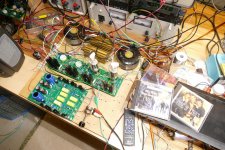
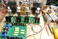
Yesterday I got the bright idea that if one big fat output tube per channel is good, two should be better, right?
I have seen, tested and heard the SCG board driving an UNSET board with one large TV sweep tube per channel. It makes 20 to 25 watts per channel, sounds great and posted some good test data for a vacuum tube based amp. The test data shown was done with the tubes being run rather hard. This is OK in a Class AB push pull amp where the average power is rather low and the idle dissipation is well below the output device's spec limit. This however is a Class A Single Ended design where worst case dissipation is seen at idle and low power output, where it will spend most of its lifetime. Conventional wisdom on tube amps is to run the tubes at 70 to 80% of spec in a class A design. These tubes are rather conservatively rated at 33 to 40 watts and there is no visible glow from the guts at over 50 watts in a well constructed tube. Not all tubes are "well constructed" and testing must be performed to find good ones if they will be pushed hard.
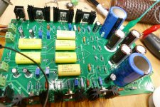
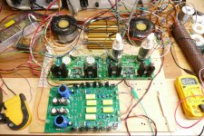
My breadboard however looked rather sad and disconnected with two empty sockets and several dangling wires, so I decided to fix that.
This picture shows two tubes in each board with the two tube / mosfet pairs wired in parallel. Each board is driven from one channel on the SCG board. Despite the "Nominal Power - 60W" sticker on the Toroidy OPT's, they will not do 30 watts across the audio range and saturation was seen at 20 watts below about 35 Hz. I decided to use a pair of Hammond 1628SEA's that I have owned since 2006. They are large, inefficient, and have never been used in an amplifier as long as I have owned them since I have always found something else that worked better in listening and measurement testing. The huge core requires more energy to flip all those magnetic domains back and forth, so they give up at least 10% of the applied audio power compared to the large Edcors, and probably close to 20% compared to the efficient Toroidy's that these are replacing. The Hammonds are 5K ohm and I need a lower impedance, so I am deliberately mis-wiring them to get 2500 ohms, which will waste more audio power.
The Hammonds have more stray capacitance and leakage inductance than most OPT's primarily because they are BIG. More wire, and more metal makes more inductance and capacitance. They have been consistently marginal in HF frequency response with an upper 3dB point in the 18 to 25 KHz range in a typical SE tube amp design like my SSE. The vacuum tube based UNSET changed that with frequency response from about 20 Hz to mid 30 KHz due to the low driving impedance it presents to the transformer. This reduces the "Q" of the resonant notch formed by the stray capacitance and leakage inductance. Listening tests with an UNSET board driving these transformers were very positive.
Running Two UNSET circuits in parallel further reduces the driving impedance to the OPT and allows for a more conservative operating point. I fired the breadboard amp up and set each tube for 35 watts of dissipation. The amp began to clip around 30 watts and hit 5.5% THD at 35 watts. I believe that this would be a 40 watt amp with a more efficient OPT. The 3 dB frequency response at 20 watts of audio output was 16 Hz to 45 KHz, a number previously unseen with these transformers. THD vs Power at 1 KHz is below. Both channels were nearly identical. It took 1.05 Vrms to drive the amp to 20 watts of output.
0.1 W 0.39% limited by 60 Hz hum
0.5 W 0.31% also limited by 60 Hz hum
1.0 W 0.30%
2.0 W 0.32%
5.0 W 0.40%
10 W 0.46%
15 W 0.48%
20 W 0.57%
25 W 0.61%
30 W 1.76%
35 W 5.51%
I decided to hook up the CD player and speakers, but that's where everything went wrong leaving me with smoke, unanswered questions, and dead parts.
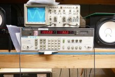
Everything was wired up, the tube heaters were pre-heated, and I brought up the power supply that feeds the SCG board first. When I switched on the power supply that feeds the output tubes the 20 amp breaker in the panel tripped. This should not happen since there is a 15 amp breaker on my workbench, and no other load was on the 20 amp breaker. This had to be a GCFI based trip. I began to unplug all of the test equipment and plug things back in one at a time trying to find the leakage path. Both of my 600+ volt power supplies were originally sold as metal scrap and had the big HP6448B had been wet before and was a bit rusty inside, but has been reliable for 15 years, and was not being used at the time. It also has both sides of the power line input switched. The 555 Volt Fluke is dead and also not used or plugged in. The 400 volt Knight Kit has been rebuilt and is powering the SCG board.
I suspected the Sorensen switcher since it was also a rescue from scrap and the second picture shows what it looked like when I got it. I decided to disconnect it and swap it with the big HP6448B. Unfortunately, I accidentally swapped two banana plugs and fed 450 volts at up to 1.7 amps into the SCG board and the vacuum tube screen grids. When I hit the power switch the fire gods danced and the smoke monster descended on all 3 boards. I had a small fan running to keep things cool so I could not see what smoked, I watched the current meter as I hit the on switch and immediately killed power when I saw it pass 1 Amp. I don't see any obvious blown stuff, but I haven't looked very carefully. I'm still looking for the reason the breaker pops.
This morning the breaker was still popping whenever I turned on the switching power supply and any other piece of test equipment, but it also popped when I turned on the scope and audio analyzer with the power supply off. I decided to move the stack of equipment but found nothing and the problem vanished. Things that "fix themselves" often unfix themselves at the most inopportune moment. I'm going to take that supply apart for a better look. While the bench is a mess, I need to look inside my Fluke 407D. It was yet another metal scrap salvage that I got on Ebay for $25 plus $45 shipping over 20 years ago. It worked when I got it and other than some loose pots, has worked fine until a couple months ago. It was built around 1970 and still contains all of its original parts. It probably needs a total rebuild.
I have seen, tested and heard the SCG board driving an UNSET board with one large TV sweep tube per channel. It makes 20 to 25 watts per channel, sounds great and posted some good test data for a vacuum tube based amp. The test data shown was done with the tubes being run rather hard. This is OK in a Class AB push pull amp where the average power is rather low and the idle dissipation is well below the output device's spec limit. This however is a Class A Single Ended design where worst case dissipation is seen at idle and low power output, where it will spend most of its lifetime. Conventional wisdom on tube amps is to run the tubes at 70 to 80% of spec in a class A design. These tubes are rather conservatively rated at 33 to 40 watts and there is no visible glow from the guts at over 50 watts in a well constructed tube. Not all tubes are "well constructed" and testing must be performed to find good ones if they will be pushed hard.
My breadboard however looked rather sad and disconnected with two empty sockets and several dangling wires, so I decided to fix that.
This picture shows two tubes in each board with the two tube / mosfet pairs wired in parallel. Each board is driven from one channel on the SCG board. Despite the "Nominal Power - 60W" sticker on the Toroidy OPT's, they will not do 30 watts across the audio range and saturation was seen at 20 watts below about 35 Hz. I decided to use a pair of Hammond 1628SEA's that I have owned since 2006. They are large, inefficient, and have never been used in an amplifier as long as I have owned them since I have always found something else that worked better in listening and measurement testing. The huge core requires more energy to flip all those magnetic domains back and forth, so they give up at least 10% of the applied audio power compared to the large Edcors, and probably close to 20% compared to the efficient Toroidy's that these are replacing. The Hammonds are 5K ohm and I need a lower impedance, so I am deliberately mis-wiring them to get 2500 ohms, which will waste more audio power.
The Hammonds have more stray capacitance and leakage inductance than most OPT's primarily because they are BIG. More wire, and more metal makes more inductance and capacitance. They have been consistently marginal in HF frequency response with an upper 3dB point in the 18 to 25 KHz range in a typical SE tube amp design like my SSE. The vacuum tube based UNSET changed that with frequency response from about 20 Hz to mid 30 KHz due to the low driving impedance it presents to the transformer. This reduces the "Q" of the resonant notch formed by the stray capacitance and leakage inductance. Listening tests with an UNSET board driving these transformers were very positive.
Running Two UNSET circuits in parallel further reduces the driving impedance to the OPT and allows for a more conservative operating point. I fired the breadboard amp up and set each tube for 35 watts of dissipation. The amp began to clip around 30 watts and hit 5.5% THD at 35 watts. I believe that this would be a 40 watt amp with a more efficient OPT. The 3 dB frequency response at 20 watts of audio output was 16 Hz to 45 KHz, a number previously unseen with these transformers. THD vs Power at 1 KHz is below. Both channels were nearly identical. It took 1.05 Vrms to drive the amp to 20 watts of output.
0.1 W 0.39% limited by 60 Hz hum
0.5 W 0.31% also limited by 60 Hz hum
1.0 W 0.30%
2.0 W 0.32%
5.0 W 0.40%
10 W 0.46%
15 W 0.48%
20 W 0.57%
25 W 0.61%
30 W 1.76%
35 W 5.51%
I decided to hook up the CD player and speakers, but that's where everything went wrong leaving me with smoke, unanswered questions, and dead parts.
Everything was wired up, the tube heaters were pre-heated, and I brought up the power supply that feeds the SCG board first. When I switched on the power supply that feeds the output tubes the 20 amp breaker in the panel tripped. This should not happen since there is a 15 amp breaker on my workbench, and no other load was on the 20 amp breaker. This had to be a GCFI based trip. I began to unplug all of the test equipment and plug things back in one at a time trying to find the leakage path. Both of my 600+ volt power supplies were originally sold as metal scrap and had the big HP6448B had been wet before and was a bit rusty inside, but has been reliable for 15 years, and was not being used at the time. It also has both sides of the power line input switched. The 555 Volt Fluke is dead and also not used or plugged in. The 400 volt Knight Kit has been rebuilt and is powering the SCG board.
I suspected the Sorensen switcher since it was also a rescue from scrap and the second picture shows what it looked like when I got it. I decided to disconnect it and swap it with the big HP6448B. Unfortunately, I accidentally swapped two banana plugs and fed 450 volts at up to 1.7 amps into the SCG board and the vacuum tube screen grids. When I hit the power switch the fire gods danced and the smoke monster descended on all 3 boards. I had a small fan running to keep things cool so I could not see what smoked, I watched the current meter as I hit the on switch and immediately killed power when I saw it pass 1 Amp. I don't see any obvious blown stuff, but I haven't looked very carefully. I'm still looking for the reason the breaker pops.
This morning the breaker was still popping whenever I turned on the switching power supply and any other piece of test equipment, but it also popped when I turned on the scope and audio analyzer with the power supply off. I decided to move the stack of equipment but found nothing and the problem vanished. Things that "fix themselves" often unfix themselves at the most inopportune moment. I'm going to take that supply apart for a better look. While the bench is a mess, I need to look inside my Fluke 407D. It was yet another metal scrap salvage that I got on Ebay for $25 plus $45 shipping over 20 years ago. It worked when I got it and other than some loose pots, has worked fine until a couple months ago. It was built around 1970 and still contains all of its original parts. It probably needs a total rebuild.
Attachments
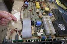
I ripped my workbench apart in an attempt to find the cause of the GCFI trips but failed to find the cause. I cleaned up the ratsnest of wiring behind the equipment and took the Fluke 407D apart to see if there was an obvious clue to its fault but found nothing obvious. I think I'll replace all of the tubes and try it again as they are all 50 years old, and I have seriously abused this thing.
I put back the power supplies and began to troubleshoot the dead amp expecting the worst. I powered up the SCG board by itself and found it to be drawing almost 200 mA instead of 60. One channel however, worked just fine and the other was dead. Voltage readings revealed a fried input fet, so I replaced it. This brought the other channel back, but the current was still high, but not as bad as before. I soon realized that one of the big blue electrolytics was getting warm and there were signs that it had vented. Oddly the characteristic stink of a vented electrolytic did not occur, or I would have looked for that first. The 100 ohm resistor that feeds that cap was a bit darker than its brother in the other channel.
I hooked everything else back up and the amp works. After about 15 minutes of testing the blue cap was quite warm but the current kept creeping downward so I connected up the CD player and the speakers. I have never heard sound like that come from these big transformers, and even with 87 dB speakers it goes quite loud. Percussion is very dynamic, and everything sounds quite real. Everything has its drawbacks, and to some this amp's worst characteristic is the 300 watts or heat it puts into the room at idle. Almost 30 years ago I built a 30 WPC SE tube amp using 211 or 845 transmitting triodes on 1050 volts. It sounded quite nice but didn't have anything close to the dynamics that this amp has. It also put over 500 watts into the room. That didn't work in my 100 square foot room in Florida, so the amp never got much play time, and it still sits on a shelf in the corner unused. It's currently 33 degrees outside, a few extra watts of heat in the basement is a good thing.
Attachments

- Home
- Amplifiers
- Pass Labs
- Schade Common Gate (SCG) Preamp