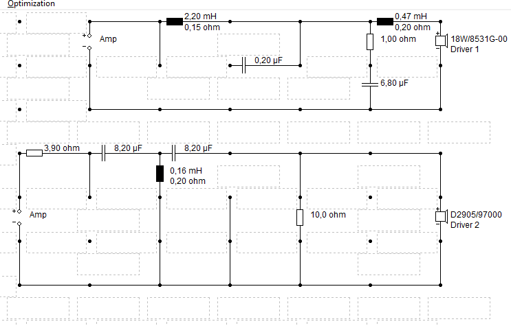
this is the actual xover with highs relaxed
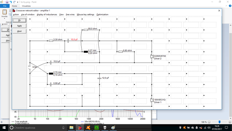
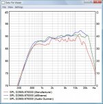
also measurement confirms the result
Hi Cucicu,
Filter17 already. It is a LR4 1700Hz above 1kHz. It is good on target above 1kHz. Also phase aligning is ok. W.r.t. power this filter is an improvement of course.
Important remark, place a resistor of about 10 Ohm in series with the 0.68uF in the woofer filter. Without the resistor you make a high frequency short circuit. Not so good for amplifier. It also smoothes the step in the woofer phase response.
I still use my own frd's.
Results
Schematic filter17 LR4 1700Hz

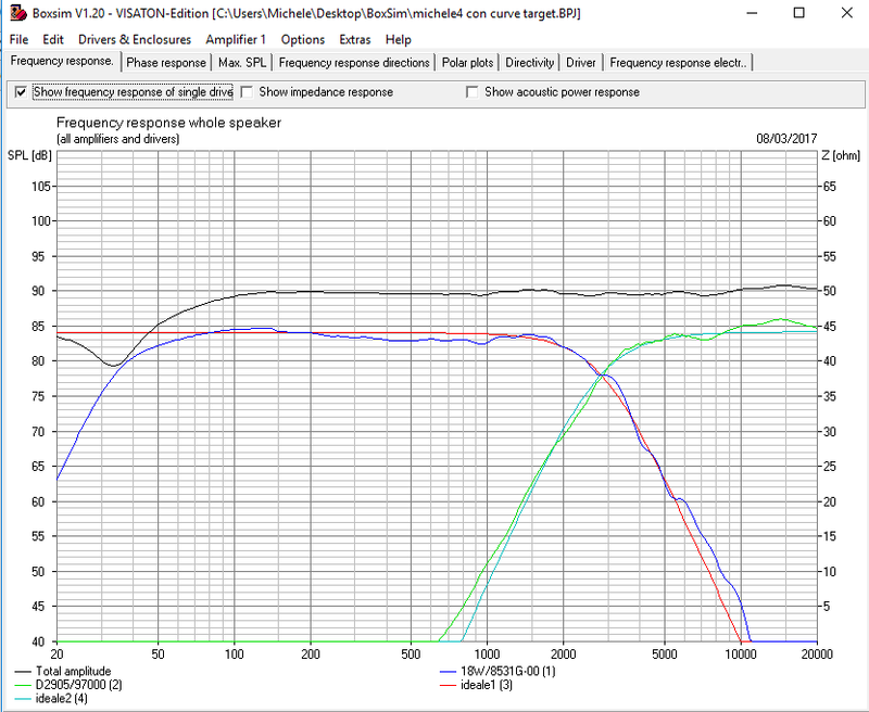
SPL filter17 LR4 1700Hz

Phase filter17 LR4 1700Hz

Not bad this filter IMO. I can understand that sound can be good.
Last edited:
FWIW, attached is my crossover proposal. It takes into account the diverging tweeter measurements and the off-axis response in a typical stereo triangle as well.
Hi Dissi,
I have simulated your filter with my frd's.
The woofer response is almost the same. Your tweeter response is about 2dB higher. I don't understand, my tweeter response without filter is conform the supplier specification, see curve below with my tweeter frd. The tweeter impedance of the model also maps perfect on the specification value.
Regards.
The results.
Schematic filter 17 Proposal Dissi

SPL filter 17 Proposal Dissi

SPL tweeter in enclosure without filter

Hi Cucicu,
Filter17 already. It is a LR4 1700Hz above 1kHz. It is good on target above 1kHz. Also phase aligning is ok. W.r.t. power this filter is an improvement of course.
Important remark, place a resistor of about 10 Ohm in series with the 0.68uF in the woofer filter. Without the resistor you make a high frequency short circuit. Not so good for amplifier. It also smoothes the step in the woofer phase response.
I still use my own frd's.
Results
Schematic filter17 LR4 1700Hz
View attachment 603890
SPL filter17 LR4 1700Hz
View attachment 603891
Phase filter17 LR4 1700Hz
View attachment 603892
Not bad this filter IMO. I can understand that sound can be good.
Very good Paul
I added the 10ohm resistor as you said.
I m listening to it and I can say that is the best filter. Maybe the definitive one.
I only ask you, with your experience, if you can make any improvement on the tweeter irregularity to make it sounding more flat. But this is it! Unfortunatelly my tweeter simulation is not accurated as yours, i don t see that bump at 2khz and dip on 3-5khz but i feel them listening
A somewhat weird question considering the point we are at, but when you tried the previous crossovers and reported paper sound, did you connect the tweeter with the correct polarity? I notice your last proposal has the tweeter connected with the same polarity as the woofer.
Why i should connect the tweeter with reverse polarity? In all filters done since now here, it goes the same polarity as woofer
Very good Paul
I added the 10ohm resistor as you said.
I m listening to it and I can say that is the best filter. Maybe the definitive one.
I only ask you, with your experience, if you can make any improvement on the tweeter irregularity to make it sounding more flat. But this is it! Unfortunatelly my tweeter simulation is not accurated as yours, i don t see that bump at 2khz and dip on 3-5khz but i feel them listening
Nice to hear!
In general you may only correct driver related SPL ripple and not diffraction related, because the last is dependent on the angle. At 15 degree off axis the tweeter SPL can look already different.
Looking to the SPL specification of this driver, you see a SPL step of 2dB in the response starting just below 2kHz. It causes the bump at 2kHz of the filtered response. I will look at it if I can improve this.
Your tweeter response is about 2dB higher.
That's explainable. Scanspeak response curves generally are very reliable IMO. But in case of the 9700 tweeter third party measurements indicate a higher level and often show a rising frequency response. Therefore I didn't use manufacturer data this time but the response from Audio Gurman (??-????????) in the hope to get closer to reality.
But it sounds dark. And in the simulation the level is terribly low, almost invisible... 😀
Attachments
That's explainable. Scanspeak response curves generally are very reliable IMO. But in case of the 9700 tweeter third party measurements indicate a higher level and often show a rising frequency response. Therefore I didn't use manufacturer data this time but the response from Audio Gurman (??-????????) in the hope to get closer to reality.
But it sounds dark. And in the simulation the level is terribly low, almost invisible... 😀
Thanks Dissi, probably the SPL is higher than specified by Scanspeak.
Unfortunatelly my tweeter simulation is not accurated as yours, i don t see that bump at 2khz and dip on 3-5khz but i feel them listening
That's because of the smoothing. Increase the frequency resolution to 599 points (that's the maximum) and you will see all the details. Unfortunately Boxsim doesn't save this setting and always returns to the low resolution mode.
PHP:
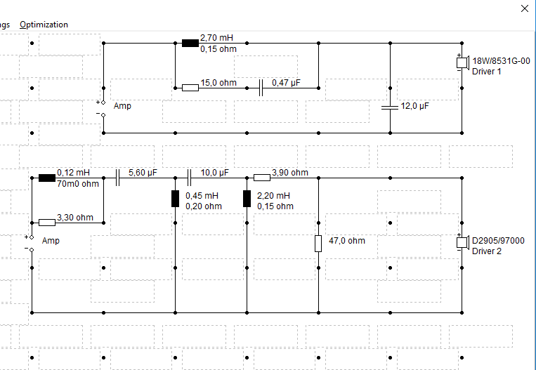
I have designed a more classic topology for the tweeter filter, but with almost the same tweeter response as filter17. It is a calculated LR4 filter out of the LR4 polynomial. In this way it has a more correct LR4 curve shape. It is less resonant at 2kHz and the overall SPL of the tweeter is more flat. This is a 8 Ohm tweeter filter, filter 17 is 4.5Ohm.
Also little modifications applied to the woofer filter.
Maybe you can try, it is up to you. You probably need some new components.
You can also try C17=5.6uF, a lttle more damped at 2kHz.
Schematic filter18 LR4 1700Hz

SPL filter 18 LR4 1700Hz

very good, it seems perfect.
I have right now made a simulation using LR4 target slope, level 85db, crossing Freq. 1700Hz. The result is similar to yours, with minor changes on the equalization of the tweeter. Sure I will try yours and mine which has that LR equalization that Troels (for example) always use with this tweeter. But he also like a dropping response from bass to highs. I would like to know what's your opinion about that.
This is the sim with targets:
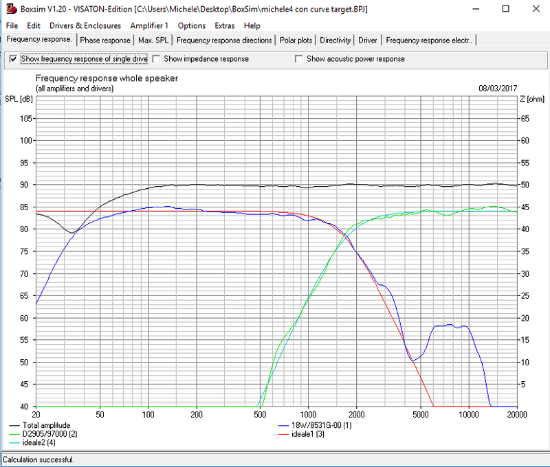
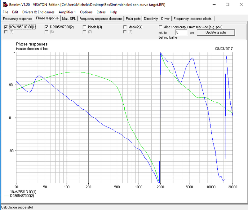
I also tried to simulate a different cross point, 2800hz LR4.
I don't know if it could be good for the beaming of the 18W, also phase tracking can be improved.
1.7khz LR4 is spectacular, but with 2.8khz it "seems" there is a "natural" notch in the range of 200-1000hz. who knows.
here we are:
I don't know if it could be good for the beaming of the 18W, also phase tracking can be improved.
1.7khz LR4 is spectacular, but with 2.8khz it "seems" there is a "natural" notch in the range of 200-1000hz. who knows.
here we are:
Last edited:
Why i should connect the tweeter with reverse polarity? In all filters done since now here, it goes the same polarity as woofer
The one I sent you (LR2) needed the tweeter reversed for phase tracking, otherwise you`d get a deep notch at the crossover frequency, thus lack of mids from both drivers and somewhat paperish sound. In addition, if you try any other LR2 design that might be simulated in the future by the other helpers here, tweeter usually needs to be reversed.
I still suggest you try some more 2nd order crossover options, the higher overlap between the drivers may force your brain think paperish sound is gone 😉
Schematic filter 10 LR2 2000Hz proposal Mario Pankov
View attachment 603586
SPL filter 10 LR2 2000Hz proposal Mario Pankov
View attachment 603589
The one above is wrong. With such polarity, the null at 2Khz is close to 32db. No idea why it comes up this way but using your .frd files appears ot produce very different results and more consistent with what I have measured. See my post and graph (149) on page 15. The shown system response there is with normal polarity, thus tweeter needs to be reversed.
I`d give you a piece of advice. Post a thread on diyaudio if anyone near you in Italy has a calibrated measurement setup and ask for help. Once he/she gets you the correct data, we can come up with a much better solution, I am sure. If not, try calling any audio instalatiors/pro sound companies and ask if you could rent a measurement rig.
Last edited:
Thank for the advice.
I will make some last proofs and buy a measurement system if i wont get anything good.
Now im working with target slopes because the LR4 at 1.7khz proposed is very good to my ears and I think that is tha right way. Only minor adjustements required.
Now my question is what is the best frequency for crossing the 18w. 1.7khz seems quite good but in most designs that tweeter is crossed at 2.8khz because of the physiological bump at 2khz and the rising response. I dont know if it could be a good idea crossing the 18w such high because of the beaming. What do you think?
The one above is wrong. With such polarity, the null at 2Khz is close to 32db. No idea why it comes up this way but using your .frd files appears ot produce very different results and more consistent with what I have measured. See my post and graph (149) on page 15. The shown system response there is with normal polarity, thus tweeter needs to be reversed.
I`d give you a piece of advice. Post a thread on diyaudio if anyone near you in Italy has a calibrated measurement setup and ask for help. Once he/she gets you the correct data, we can come up with a much better solution, I am sure. If not, try calling any audio instalatiors/pro sound companies and ask if you could rent a measurement rig.
Mario,
I don't understand your remark about filter 10. The drivers are in opposite phase in that schematic and it has to be. Look to the dots on the driver symbols, they are opposite.
At this moment there are no measurements by Cucicu, that is right, but when its drivers are not too much different w.r.t. the specification the simulation at this moment can come close to reality.
Divers have a minimum phase behavior in the passband. Via a minimum phase transform on the specification curves the phase responses can be obtained and the responses come close to reality.
When you are using a measurement system sampling at 44kHz, the phase resolution at 4400Hz is also +/- 36 degrees, that is also a lot.
But I agree for sure you have to do the measurements but in this case I will help Cucici to obtain the best result now. I think he does hear it all 🙂.
Thank you Paul, measurements would be needed but in this case (as in many others) i trust the measures made by dibirama. He uses real parts on infinte baffle and measure them very well, so I expect the simulation is quite similar to reality. I have never had issues with previous designs but this time (maybe because drivers are "revelator") I had many difficulties to match the crossover point.
When I mounted the crossover17, the difference respect to previous design was very audible. No characterized sound and no listening fatigue; no details masking and confusion anyway. But this is a little adjustable.
When I mounted the crossover17, the difference respect to previous design was very audible. No characterized sound and no listening fatigue; no details masking and confusion anyway. But this is a little adjustable.
very good, it seems perfect.
I have right now made a simulation using LR4 target slope, level 85db, crossing Freq. 1700Hz. The result is similar to yours, with minor changes on the equalization of the tweeter. Sure I will try yours and mine which has that LR equalization that Troels (for example) always use with this tweeter. But he also like a dropping response from bass to highs. I would like to know what's your opinion about that.
I can only tell what my experience is till now with overall SPL shape.
Using high slope filters I make the overall SPL flat, low to high. A loss of 2dB at high frequency makes the sound even dark.
Using low slope filters like LR2 a slow roll off of 2dB low to high is the best in most cases. I have not a good explanation for it, but I think it has to do with more low frequency power of the tweeter in such systems. So the overall power response is also different.
I prefer high slope filters, they gave me the best results till now. Like LR4, B3 and elliptical. I have tried out a 5th order elliptical filter in a system. It is the best sounding result I get till now.
IMO higher order filters are sounding more pure, less coloured. Low order often do sound more coloured, I don't like that.
I don't want to make a statement concerning this item, it is too complex to understand. I only give my own practical experience.
I completely agree, our experiences are the same 🙂
Right now, i think your filter 18 is an improvement of the 17th, if we decide to cross a 1.7khz.
Have you seen my sim of the 2.8khz cross point? maybe is too high, maybe 2khz is better . I do this because I would like the 18w sounds as high as possible, but I know the beaming problem.
would you try to simulate something like 2khz -2.8khz crossing point LR4 and evaluating phase and off axis response? with filter 17 phase is perfect, not also with mine 2.8khz sim.
I also like symmetrical cap value on tweeter like ProAc design 🙂 🙂 🙂
Last edited:
- Home
- Loudspeakers
- Multi-Way
- Scan-Speak crossover help