Hi Salas,
I am building one of your older SSLV1.1 boards, the negative PS.
It has a BC 560 listed but this is not available anymore.
I have found some alternatives on Mouser but am unsure which parameters are most important. Can you advise the best replacement?
See attached selection.
Hi,
See post#1 last paragraph.
Do you guys have a coming GB for this?
I'm not about to copy it, but I'm sure I will not wait months.
Do you guys experience that this circuit would be superior for a headphone amp, comparing to a Jung superreg?
Thanks,
JG
Hi, Did you get a conclusion in this question?
I'm considering to build a jung superreg. (earlier I've built a salas v1.3) and would be curious for others' sound comparism)
Looks like patience will be a virtue and I will need to wait for the next GB.
In the meantime I will to build up the DAM1021 using a Super Regulator based on the Jung circuit, until I can swap it out with the SSLV1.3.
I have read that Shunt regulators have better sonic performance that the super regulated psu. I would be interested to learn why?
Did you get any result?
Are there Gerbers somewhere for this? I looked through the first ten pages or so and didn't see them.
HI Salas,
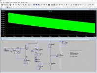
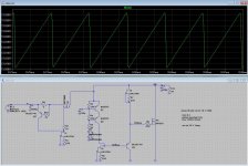
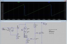
I would like to build your v1.3 (pos and neg) before that I thought it is a good idea to modell it in LTSpyce. but for me a high frequency oscillation is shown. What am i doing wrong?
Thanks in advance,
Szabolcs
I would like to build your v1.3 (pos and neg) before that I thought it is a good idea to modell it in LTSpyce. but for me a high frequency oscillation is shown. What am i doing wrong?
Thanks in advance,
Szabolcs
Attachments
Last edited:
And a small question if I may.
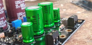
I am slowly getting my boards populated and I seem to have used green led for some reason. Is this OK?!
Thanks
I am slowly getting my boards populated and I seem to have used green led for some reason. Is this OK?!
Thanks
Yes its OK. They will just up the minimum adjustable voltage vs red.And a small question if I may.
I am slowly getting my boards populated and I seem to have used green led for some reason. Is this OK?!
Thanks
HI Salas,
I would like to build your v1.3 (pos and neg) before that I thought it is a good idea to modell it in LTSpyce. but for me a high frequency oscillation is shown. What am i doing wrong?
Thanks in advance,
Szabolcs
I see nothing weird when running similar .tran parameters in my original modeling. Don't know, change M1, JFETs, BC models in your analysis? They don't directly correspond to BOM many of those you used. Put some ESR and ESL in your electrolytics modeling also.
Attachments
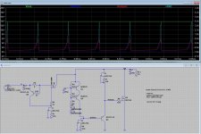
Salas, in your experience, is what he is showing - 20 mV at around 4400 Hz - going to cause a noise issue? I was looking at using this regulator with a B1 Korg so it would go through another set of filter caps too.
Thank you. I am looking forward to building this.
-Geoff
Thank you. I am looking forward to building this.
-Geoff
Yes the ESR was the solution. If I put e.g. 0.1ohm to the output CAP than immediately it is OK.I see nothing weird when running similar .tran parameters in my original modeling. Don't know, change M1, JFETs, BC models in your analysis? They don't directly correspond to BOM many of those you used. Put some ESR and ESL in your electrolytics modeling also.
Thanks for confirming the green LED.
I read in another thread about Muse ES BP caps actually having a better orientation. I did notice the longer lead and the lettering on the label being aligned.
Did I put these in how one would deem the best way? I learned of this after soldering them in!
I read in another thread about Muse ES BP caps actually having a better orientation. I did notice the longer lead and the lettering on the label being aligned.
Did I put these in how one would deem the best way? I learned of this after soldering them in!
Attachments
That's not a purely technically explained orientation preference but a subjective recommendation that I haven't explored. These non polar capacitors are most possibly made by the same assembly machines that produce vastly bigger quantities of polar capacitor types, and that's why they retain a standard legs length difference I would think. A difference that of course serves no essential electrical polarity notice anymore in a bipolar type like the Muse ES.
i think it is a long shot but i thought i might ask.... 🙂
would it be feasible to setup two separate positive regulators with slightly different output voltage, and then connect their positive voltage to each side of a given load to create a low voltage regulator? I know there are single supplies available for that purpose, including the digital version of the regulator described here.... but i thought it may be another avenue to have more flexibility...
would it be feasible to setup two separate positive regulators with slightly different output voltage, and then connect their positive voltage to each side of a given load to create a low voltage regulator? I know there are single supplies available for that purpose, including the digital version of the regulator described here.... but i thought it may be another avenue to have more flexibility...
Whatever theoretical voltage sources combination is also doable with regulator outputs. A common reference return point is needed so to correlate. In case of utilising a level difference between same polarity, the load should be floating.
- Home
- Amplifiers
- Power Supplies
- Salas SSLV1.3 UltraBiB shunt regulator