Yes. By bridging the S & F outputs at their output connectors with short jumpers. Then just thick +0- wires. That worked with a mono Bib between channels interfacing in an early DCG3 beta. Else it was interacting with that shunt PSU. Had long rail Kelvin cables and was showing trouble there at about 1MHz if I remember well. But it also had positive and negative sections i.e. a normal ground, not a stacked positives midpoint like your config.
That's cool. Looks like a sonic weapon 😎
Thank you. I have really been enjoying listening to headphones but as a pre-amp the DCG3 really sings. It is like listening to my music collection with fresh ears.
BTW did you ground the pots metal bodies?
Not yet... will do it today 🙂
Will also try the sens - to + EL cap... will use 50u there
He can sever the ground plane at midpoint also
As you recall I had mentioned about hum when SLB's are connected and about the weird hum when I touched the circuit of the left channel. Not finding any issues with the build I decided to swap transformers from one side to another. This eliminated the hum that I heard when the circuit was touched. Perhaps one of the transformers has more leakage than the other and re positioning it solved that issue? Very quiet except for very slight hiss from the speakers.
I was still bothered by why there was a hum/buzz when SLB's were connected so finally I shorted the lifted end of the R7's back to PCB G and that resulted in no hum/buzz with SLB's connected. Maybe you can explain why.
Listening with R7's ends grounded or lifted I could hear no difference in sound. So I decided to ground them and connect the CL60's. I also paralleled a cap with each CL60 as you had earlier suggested. At the speaker it sounds just as quiet as the earlier setup.
SE to balanced conversion works even without R7's lifted. I have tested it by making leads that connect directly to XLR pin 2 and 3 and they work fine. As per Kosta's request I tested by connecting G to In- and feeding the SE signal reference there and that works fine too.
Thanks for you help.
nash
Grounding the metal parts of the pots greatly reduced the buzz. (The 50u caps between sense wires did nothing).
Thank you Salas.
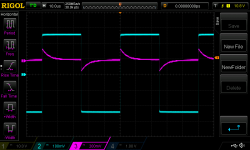
Now I discovered another strange behaviour while scoping the inputs versus outputs... When feeding a square wave into Right channel I see a distorted square on the output of the Left chanel.
Where does this crosstalk come from ?
Thank you Salas.
Now I discovered another strange behaviour while scoping the inputs versus outputs... When feeding a square wave into Right channel I see a distorted square on the output of the Left chanel.
Where does this crosstalk come from ?
Attachments
@nashbap
Explanation could be the unnecessary widening of loop area with lifted R7s. That is why I had talked one way grounded coax instead of simple wire.
But, hey, it works either way. So no worries. It maybe even sounds a bit more transparent now after optimized. Congrats.
Explanation could be the unnecessary widening of loop area with lifted R7s. That is why I had talked one way grounded coax instead of simple wire.
But, hey, it works either way. So no worries. It maybe even sounds a bit more transparent now after optimized. Congrats.
Grounding the metal parts of the pots greatly reduced the buzz. (The 50u caps between sense wires did nothing).
Thank you Salas.
Now I discovered another strange behaviour while scoping the inputs versus outputs... When feeding a square wave into Right channel I see a distorted square on the output of the Left chanel.
Where does this crosstalk come from ?
Usually from rails interaction or ground wiring interaction. Or interaction in the measurement loop.
Nicely shaped main squarewave BTW.
Yes, now the lines in the scope are free of dust. Been ploting response and never did find anything like this.
It is flat to 2megahz and reduces gain from 3X to 2.7X at 3megahz
It is flat to 2megahz and reduces gain from 3X to 2.7X at 3megahz
That's weird, indeed! It doesn't work in my setup with R7 grounded. I' ll check it again to be sure but I think the shunt volume control plays a role here.SE to balanced conversion works even without R7's lifted. I have tested it by making leads that connect directly to XLR pin 2 and 3 and they work fine. As per Kosta's request I tested by connecting G to In- and feeding the SE signal reference there and that works fine too.
Thanks for you help.
nash
If you experience issues with the transformers check for correct phase at the secondaries. 18V AC accross each secondary, 36V AC accross both.
That's weird, indeed! It doesn't work in my setup with R7 grounded. I' ll check it again to be sure but I think the shunt volume control plays a role here.
If you experience issues with the transformers check for correct phase at the secondaries. 18V AC accross each secondary, 36V AC accross both.
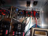
Here's the money shot.
The atten is in the max position which makes it an open between the IN+ and In- and is completely out of the equation just like you have it.
Red wire(signal) to In+, black wire joining In- and Pcb G and green wire(signal reference) also to G. Notice the short 1/4 in wire soldered between the R7 link and G that I have put in to which green wire is attached. Meter is reading between the two Line outs.
nash
Attachments
It seems correct yet strange. I' ll check mine ASAP.
BTW, I see you are running two wires from DCSTB GND to DCG3. This may be the reason for hum.
BTW, I see you are running two wires from DCSTB GND to DCG3. This may be the reason for hum.
D.Self and maybe some others have analysed that attenuator style and told us it is not good.
Something to do with the attenuations of CM and DM interferences.
I used to think this simple rheostat attenuator maintained the balanced impedances and thus was perfect, until I read D.Self, then I stopped recommending it.
In the article that I referenced by Doug Self he refers to using a microphone preamp as a line input by using a balanced attenuator. He essentially says that in a U type attenuator the differential signal(DM) is attenuated but the common mode signal (CM) is not. He claims that in an arrangement with two decks each going to ground, CMRR is preserved to a net higher result even though resistor tolerances will deteriorate the CMMR.
While that may very well be the case, and lets just assume that we can build a balanced attenuator with two decks per channel with matched switching, perfectly matched resistors and inconsequential solder joints throughout, will it really sound better than one without all that extra complexity?
Greater minds than mine have indicated that in a balanced setup the U attenuator sounds best. I am here to build and learn and you as others have helped tremendously with furthering my understanding over the past few years. If there is a design for a balanced attenuator that sounds better I would love to try it. If you are aware of one please share it with us.
Thanks.
nash
It seems correct yet strange. I' ll check mine ASAP.
BTW, I see you are running two wires from DCSTB GND to DCG3. This may be the reason for hum.
Good observation. I had removed one thinking that there was a ground loop formed but it made absolutely no difference. As noted all is quiet now.
nash
It seems correct yet strange.
A bridged output load connects the feedback networks also
Yes, now the lines in the scope are free of dust. Been ploting response and never did find anything like this.
It is flat to 2megahz and reduces gain from 3X to 2.7X at 3megahz
Sans pot it can be very fast
So, you have two transformers and two DCSTB. Right? When you power up any one channel with one DCSTB no problem. When you power up both channels with both DCSTB there is a problem. Right?
If I got the breakdown well, then some short must be existing between the two power sides. If you look up close the relay and IC socket pins solder joints which are the busiest places, is there any solder bridge? Or anywhere else for that matter, like at the trimmers, at the small transistors, etc?
When much current seems to be drawn, measure the Vgs of both sides Mosfets and compare the readings. Also the voltage drops across Q1, Q2, R3. Are they comparable? Maybe a small transistor is shorted?
I have performed the measurements on the Mosfets, Q1, Q2 and R3. Voltages all match closely. I have removed and checked all active components with the Atlas, replaced the relay with another and checked all of my soldering. Also double checked secondary's on the transformers for the DCSBT still seeing -17.2-0-+17.2 and -17.4-0-+17.4 on the outputs.
I am going to shelf the preamp for now and I am ordering another set from Teabag. Murphy is working overtime on this project!!
Load the supplies with 100-150 Ohm power resistors per polarity without being connected to the pre. See how they behave. Maybe the problem is in the supplies.
I don't understand this completely but, does it matter that Nash hasn't put opamps on?A bridged output load connects the feedback networks also
- Home
- Source & Line
- Analog Line Level
- Salas DCG3 preamp (line & headphone)