He should, with a dummy load across phase outputs, also to scope each phase output individually would be the most illuminating
Mysterious issue to have checked everything on the main board and in the PSUs alone but having overcurrent problem when combined. Does it work if a mono PSU is shared between audio channels?
The electrolytic capacitors and all kind of diodes on the audio board are correctly oriented, yes?
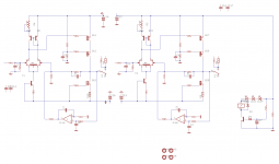
yes they are. Salas would you perhaps have a copy of the complete audio schematic that shows everything as opposed to just the one channel schematic. Perhaps I am overlooking something and seeing the complete picture might make the difference.
Thanks
David
Thanks
David
Apologies if I've missed this previously but which way round do J1/J2 (uPA68HA) go? I can't identify the manufacturer to look up their datasheet. Thanks.
Apologies if I've missed this previously but which way round do J1/J2 (uPA68HA) go? I can't identify the manufacturer to look up their datasheet. Thanks.
See Post#25 of this thread for datasheet
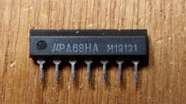
Merci beaucoup. Mine don't look like that datasheet though, there isn't the 45 degree notch in one corner, see attached photo.
It's allright, it's the N of the old Nec Logo with the stylised N embossed on left (pin1).
Be carefull when soldering, the pcb layout is mirrored between left and right channel of the board. Upa on left has pin 1 on left and Upa on right is reversed (180° rotation), pin 1 on right (relative to top / front view of the board).
See Teabag's blog : http://www.diyaudio.com/forums/blogs/tea-bag/1340-salas-dcg-3-preamplifier-dcstb-power-supply.html
Ah right, thanks again. So the left pin in my photo is 1D on the PCB, just to be sure.
Thanks for the link to Tea-Bag's blog too - I looked for it yesterday but only found his Group Buy blog.
Thanks for the link to Tea-Bag's blog too - I looked for it yesterday but only found his Group Buy blog.
Ah right, thanks again. So the left pin in my photo is 1D on the PCB, just to be sure.
Thanks for the link to Tea-Bag's blog too - I looked for it yesterday but only found his Group Buy blog.
1D : not sure, I do not have the pcb under my hand and photos are'nt good quality enough, but pin 1 are identified by the white marker on silkscreen.
1D= Drain one
Left hand channel's μPA faces the inputs/outputs connectors, right hand channel's μPA faces the MOSFETS. That's how they should be populating the board.
In other words: Where the pin designations on the silkscreen are, each chip's type & logo printed face should also be.
Left hand channel's μPA faces the inputs/outputs connectors, right hand channel's μPA faces the MOSFETS. That's how they should be populating the board.
In other words: Where the pin designations on the silkscreen are, each chip's type & logo printed face should also be.
- Home
- Source & Line
- Analog Line Level
- Salas DCG3 preamp (line & headphone)