Help. I have completed my DCSBT and DCG3. DCSBT works like a champ 17.3vdc and 17.4vdc from the two outputs.
DCG3 not so good. What is the problem appears to be on the left channel. If I power the right channel by itself after a few seconds the LEDs come on and I am able to set the offset.
I am using a light bulb on the AC side and when I connect the left channel with or without the right channel connected the bulb does not fully dim, so a problem somewhere.
I have checked location and values of all passive components and removed the transistors and checked them. Everything seems to be ok.
I am stumped. Obviously I am missing something.
I was concerned maybe I didn't mount the J1-J2 properly. But looking at photos of other builds I believe I have it installed correctly. This is the one device I have not removed to test. Perhaps it is not working?
Any thoughts or guidance appreciated.
David
Attachments
Salas, I have 1.24v across R10 on right channel and 1.22v across R10 on left channel. The three red LEDs are glowing dim and all of the bar LEDs on the power supply are out.
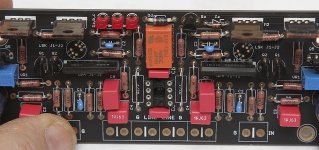
Suggest checking your solder joints again. Check the soldering on the relay 4th pin left side. Seems strange in the pic.
nash
nash
OK I have a problem.
You will recall that when I tried to connect the SLB's I got a hum. I accidentally discovered that it is confined to the left channel. A multimeter probe connected to a MM in the off position when touched to any point of the DCSTB or even my finger touching it produces a hum in the speakers whether it is the AC connections or the DC outputs or any of the diode or resistor points. And if the probe is touched to a G point of the DCG3 there is the same hum. Touch the probe to other points on the DCG3 like IN no hum. Do the same thing on the right channel DCSTB and DCG3 and no hum anywhere.
Before I remove and do substitutions thought I should ask for help. Cant see anything obvious. All wiring is tight.
Salas I have not yet put in the opamps. Differential offset is never greater than 8mv and when hot usually under 3mv. I have input transformers at my power amps. My intention was to listen for some time then insert the opamps and compare but too busy playing around with it . Having fun and learning. At least I have narrowed the hum to only one side.
Thanks. nash
I did do a reflow on the entire board. Same problem, powering both channels results in the bulb test staying bright. Powered separately no problem. Both R10s are still in the 1.24v range. VR1 has no effect on the offset for the left channel.
If I am reading your descriptions and diagrams correctly you have separated the two wire input signal into two routes. This breaks the "close coupled" rule for signal wiring. And applies to input wiring as well as output wiring.OK I have a problem.
You will recall that when I tried to connect the SLB's I got a hum. I accidentally discovered that it is confined to the left channel. A multimeter probe connected to a MM in the off position when touched to any point of the DCSTB or even my finger touching it produces a hum in the speakers whether it is the AC connections or the DC outputs or any of the diode or resistor points. And if the probe is touched to a G point of the DCG3 there is the same hum. Touch the probe to other points on the DCG3 like IN no hum. Do the same thing on the right channel DCSTB and DCG3 and no hum anywhere.
Before I remove and do substitutions thought I should ask for help. Cant see anything obvious. All wiring is tight.
Salas I have not yet put in the opamps. Differential offset is never greater than 8mv and when hot usually under 3mv. I have input transformers at my power amps. My intention was to listen for some time then insert the opamps and compare but too busy playing around with it . Having fun and learning. At least I have narrowed the hum to only one side.
Thanks. nash
You must keep the signal pair together all the way from source to receiver.
You either use coaxial, or twisted pair.
I did do a reflow on the entire board. Same problem, powering both channels results in the bulb test staying bright. Powered separately no problem. Both R10s are still in the 1.24v range. VR1 has no effect on the offset for the left channel.
Do you have individual transformers or individual secondaries for the PSUs?
Help. I have completed my DCSBT and DCG3. DCSBT works like a champ 17.3vdc and 17.4vdc from the two outputs.
DCG3 not so good. What is the problem appears to be on the left channel. If I power the right channel by itself after a few seconds the LEDs come on and I am able to set the offset.
I am using a light bulb on the AC side and when I connect the left channel with or without the right channel connected the bulb does not fully dim, so a problem somewhere.
I have checked location and values of all passive components and removed the transistors and checked them. Everything seems to be ok.
I am stumped. Obviously I am missing something.
I was concerned maybe I didn't mount the J1-J2 properly. But looking at photos of other builds I believe I have it installed correctly. This is the one device I have not removed to test. Perhaps it is not working?
Any thoughts or guidance appreciated.
David
Did you remember to follow the guide ?(short the input's to GND, when trying setting offset and so)
Not to sound ugly or like, but i really must tell you should have been a little more carefull soldering, and placing youre part's straight on line if you know what i mean.
Jesper.
Last edited:
The plank is dead; long live the plank.
My DCG3 is now well on it's way to being cased in a chassis from Modushop and is sounding excellent; so much so that I think my VTA SP14 valve pre is in a sweat thinking that it has met it's match or even superceded😉
Salas I must owe you a whole raft of drinks by now what with the DCB1;various power supplies and now the DCG3 all enhancing my listening pleasure over the past few years; so a huge thank you from me


So, you have two transformers and two DCSTB. Right? When you power up any one channel with one DCSTB no problem. When you power up both channels with both DCSTB there is a problem. Right?
If I got the breakdown well, then some short must be existing between the two power sides. If you look up close the relay and IC socket pins solder joints which are the busiest places, is there any solder bridge? Or anywhere else for that matter, like at the trimmers, at the small transistors, etc?
When much current seems to be drawn, measure the Vgs of both sides Mosfets and compare the readings. Also the voltage drops across Q1, Q2, R3. Are they comparable? Maybe a small transistor is shorted?
Yes to both channels having the problem when powered from both DCSTB. Thanks for the advice, I will research each point.
Thank you
Thank you
drpro !
In post # 1551, i made som critism to you, which i really regret... 🙁
I donno was went into me, i normally don't behave like that!; maybe you could accept my appologise???
So long story short: sorry to have been written that mate 🙂
Hope you fogive me ?
Best wishes, and good luck with youre faultclearance.
Jesper.
Hi!.
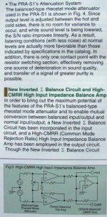
Looking the images from Nash's preamp, I like the solution for volume attenuation. But thinking about something even more simple I remembered an old thread about "Passive balanced volume control using a single attenuator" and this would be a possible solution.
What do you think about?
Looking the images from Nash's preamp, I like the solution for volume attenuation. But thinking about something even more simple I remembered an old thread about "Passive balanced volume control using a single attenuator" and this would be a possible solution.
What do you think about?
Attachments
Yes straight is the shortest distance between two points. I really did go back over the entire board and reflow each solder point.
When I have time tomorrow, I am going to revisit the preamp taking Salas advice.
Thanks all
When I have time tomorrow, I am going to revisit the preamp taking Salas advice.
Thanks all
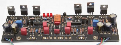
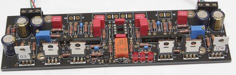
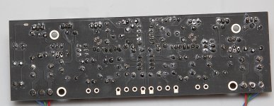
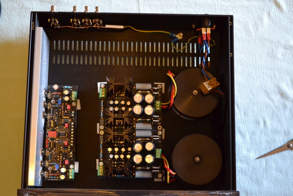
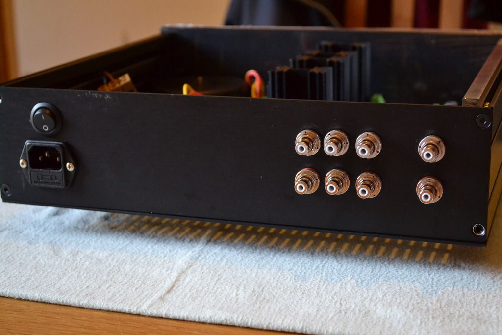
Please see pics of my completed balanced build.
nash
__________________
F5TV3, AVC, BA3 bal pre
What are the green things you're using for fuses on the PS boards?
- Home
- Source & Line
- Analog Line Level
- Salas DCG3 preamp (line & headphone)