Your build looks excellent. Congratulations.
What are those (Shinkoh?) resistors in series with the inputs for?
What are those (Shinkoh?) resistors in series with the inputs for?
Your build looks excellent. Congratulations.
What are those (Shinkoh?) resistors in series with the inputs for?
Thank you Salas and Kostas.
Yes they are matched 13K Shinkoh's. Direct from the XLR pins 2 and 3 to their respective inputs with a shunt attenuator between the PCB inputs. No unnecessary wiring needed. Maintains a very high CMRR this way. I made the shunt with Takman Rey metal films. After much experimenting on my BA3B I found this combo gives me the best balance of clarity and sonic density that I need for classical music. Better than TX2575 which I also tried. In my opinion the attenuator choice makes a very huge difference in overall sound.
You may also notice that I have used a couple of PTF's and RN60E's(25ppm, 0.1%) in key positions.
I do not have any connection from DCG3 G to chassis.
nash
Is there any chance to test it with SE signal at one phase input and the other grounded to see if you get proper balanced output?
Is there any chance to test it with SE signal at one phase input and the other grounded to see if you get proper balanced output?
This is what I tested. Note R7's are linked. I connected the SE output of my CD player using a 1khz test signal on a CD. +of signal to input on DCG3 and signal reference to the G on the DCG3. I adjusted the out put of the CD player to get around 0.25VAC. I measured around 0.5VAC between Line and G on the phase to which the signal was connected and 0.25VAC between the Line and G on the other phase. Measuring across the two Line outs resulted in 0.75VAC which is 3x, the gain I have set for.
Next I shorted the R7's link to G on the PCB simulating what would be if the R7's were grounded as per the schematic and measured again. This time I again got 0.5VAC on the phase that was receiving the signal and 0VAC between Line and G on the other phase. However, to my surprise I still got the full 0.75VAC between the two Line outs.
nash
Ready to purchase a stepped attenuator. From my reading either a 20k or 10k. Open to thoughts and suggestions.
Thanks
Thanks
...However, to my surprise I still got the full 0.75VAC between the two Line outs.
nash
This and the ground to chassis problem may be because of the shunt volume control?
This and the ground to chassis problem may be because of the shunt volume control?
I did the test before any of that was connected. I also have the same setup on the BA3B. Today I will try SE input again and let you know. My interest in the first test was primarily to verify that the boards were working, so I want to make sure I am not giving you incorrect info.
nash
How many K is the pot?
Is the question directed to me?
Each series resistor is 13K and with attenuation in my normal listening position around -22db the shunt is at 2200R, so one can say that if each was separate then 13k + 1100R =14100R at -22db. In my BA3b the series are 10k each with a correspondingly smaller shunt again at -22db, gain structure of both is similar around 3x.
nash
Is the question directed to me?
Yes, the question was for you
Ok I've searched to try and find anything on board buys. If anyone can direct quickly to where I would go to get boards I would appreciate. Also any support boards like power supply or input switching.
Thanks
Thanks
So its a non constant impedance shunt type configuration
At any attenuation position there will be only three resistors in the circuit-the two series and the one selected shunt.
OK so I did a bit of testing.
As mentioned before the shunt portion of my attenuator is between the two IN's on the board. I turned the vol to its max in which position there is an open so essentially there is no shunt between the two IN's.
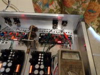
I took the SE output of a CD player and outputted a 1khz test tone and adjusted the output to around 0.25VAC. Using test clips I connected the red signal wire in the pic to the + in on the board and the green signal reference to the -In. The meter is reading the differential output between the two Line outs and you see it is around the expected 0.75VAC.
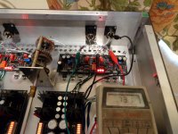
Next I connected a black test clip between the R7's link and G on the DCG3. The pic shows me connecting one end to the output XLR pin 1 which is presently connected to G on the DCG3. Once again the differential output shows around 0.75VAC.
This tells me that that I can get a differential output even if R7's are not linked. Why? I think it is because the G's of the two individual gain modules(if you call them such) are linked thru a common Ground plane on the DCG3 board.
So in short to get diff output with an SE input either have an RCA input on the DCG3 that connects the signal to XLR pin2 and SE signal reference to pin3 or just make an interconnect with an XLR plug similarly wired. Pin1's to chassis on both input and output.
nash
As mentioned before the shunt portion of my attenuator is between the two IN's on the board. I turned the vol to its max in which position there is an open so essentially there is no shunt between the two IN's.
I took the SE output of a CD player and outputted a 1khz test tone and adjusted the output to around 0.25VAC. Using test clips I connected the red signal wire in the pic to the + in on the board and the green signal reference to the -In. The meter is reading the differential output between the two Line outs and you see it is around the expected 0.75VAC.
Next I connected a black test clip between the R7's link and G on the DCG3. The pic shows me connecting one end to the output XLR pin 1 which is presently connected to G on the DCG3. Once again the differential output shows around 0.75VAC.
This tells me that that I can get a differential output even if R7's are not linked. Why? I think it is because the G's of the two individual gain modules(if you call them such) are linked thru a common Ground plane on the DCG3 board.
So in short to get diff output with an SE input either have an RCA input on the DCG3 that connects the signal to XLR pin2 and SE signal reference to pin3 or just make an interconnect with an XLR plug similarly wired. Pin1's to chassis on both input and output.
nash
Attachments
Nash,...I connected the red signal wire in the pic to the + in on the board and the green signal reference to the -In....
nash
I believe you should connect the red wire to the +in and the green wire to GND. The -in should also be connected to GND. And of course, R7 lifted. I think this is the proper way to convert SE input to balanced output and preserve functionality of the volume control. Please try it this way and let us know the results.
Nash,
I believe you should connect the red wire to the +in and the green wire to GND. The -in should also be connected to GND. And of course, R7 lifted. I think this is the proper way to convert SE input to balanced output and preserve functionality of the volume control. Please try it this way and let us know the results.
Sure will let you know tomorrow. Indeed my BA3B is wired the way you say but that is to avoid a 6db gain going from balanced to SE.
nash
- Home
- Source & Line
- Analog Line Level
- Salas DCG3 preamp (line & headphone)