Is that strange? My brother makes all the same observations as I do, and I never give him any tips beforehand.
It may just be I'm using particularly crappy capacitors. I wouldn't know.
I never expected the input cap would have much of an effect, but it does have one, enough for me to not want to "downgrade". I thought it would be easy to tweak the amp and make it sound great, until it became obvious that cap choices would make or break. I will say that by far the biggest change in terms of impact on listenability of the music however is the compensation. Too much, it will be muffled, too little and it will be harsh. Beyond this, changing input and feedback caps make less noticeable improvements (but of a different type - like apples and oranges). What seems to change is what instruments are brought to the foreground. For some caps, treble dominates, for others it will not be so, but the music will be dull instead. In between these two extremes is where I aim.
Also, consider that I'm driving a 5.4ohm speaker with a headphone amp qualified for 24ohms max power. It will increase most distortions to "high" levels, including those of the feedback DC blocking cap.
Of course, I may be only fooling myself into thinking I hear something I don't. Then again, I would hate to fool myself into thinking what I hear is only in my head.
- keantoken
In restrospect, Iko, your concerns (if I intuit your post correctly) are quite valid.
Firstly, I didn't actually check my observations against my brother's for the input cap change. Before my brother auditioned, I also switched my soundcard to mono mode, whereas before I was just shorting the channels together for mono mix (LOL!!!), and to me this also had a large effect on the sound quality. So I didn't actually have the opportunity to scientifically check every upgrade.
Despite this, my impression is that each of these upgrades improved the amplifier, and after listening so far, I haven't received any impression to the contrary.
- keantoken
Hey kt, I wasn't making a statement. Was just curious. I have yet to hear the difference two different capacitors make in a circuit. My hearing at normal volume seems ok up to 16kHz.
At times I tested myself, I've heard up to 16KHz and 18KHz. The 18KHz test was more recent, but I suspect my hearing changes over time and with different experiences in day to day life.
Whenever I get that prototype working, maybe I should send it to you first, to see if the component choices make a difference to you.
- keantoken
Whenever I get that prototype working, maybe I should send it to you first, to see if the component choices make a difference to you.
- keantoken
I had the rather interesting idea of adding a L||R at the output before the load. I previously thought this was called a Zobel but... Whatever.
At first I thought it was silly that I am considering using a technique commonly needed for power amplifiers on a headphone amp, but after investigation in the simulator, I am beginning to think that it's even more silly NOT to do it this way.
It is extremely affective against capacitive loads, and gives better performance usually than doping up the amp on compensation. With a small L||R combo at output, my amps simulated can drive several tens of nF with no more than -8 degrees phase lag at 100KHz at the actual load. If we instead omitted the L||R, and tried to compensate the amp, we would both destroy high-frequency THD, and 100KHz phase shift. Not only this, but the L||R will make compensation characteristics more consistent with various loads, so the amp can consistently perform well. All signs seem to point in favor of the L||R.
And as such I am going to test a .5nH||33R combo on my prototype. I believe I can get away with sacrificing some purism, considering what I stand to gain if this turns out well.
- keantoken
I have been calling "it" a Thiele Network.
Thiele proposed this with two locations of the C+R. Either before the L//R or after the L//R.
I decided to try adopting both locations, forming a Pi filter.
C1+R1 at the PCB to act as a high frequency load right next to the output devices incorporating minimum inductance in the circuit route for HF.
Then L1//R2 in the route from PCB to the output terminals. This to minimise the effect of chassis on the L and for maximising the distance from L to the PCB components.
Finally the C2+R3 across the output terminals. This acts as a fixed HF load and as an RF attenuator for interference and/or back emf from the outside to the feedback loop.
Russ' Diamante had Thiele Network on the output of his headphone/line driver PCB.
For an 8ohm Power Amplifier I use:
R1=10r
R2=5r
R3=5r
C1=47nF
C2=68nF
L1=0.5uH to 1.5uH
At VHF the amp sees ~5r as a load fed through the 47nF & 68nF capacitors.
Thanks for the info Andrew. I was wondering about this:
For MOSFET amps I can understand this, if the aim is to keep trace inductances from resonating with the MOSFETs. However with BJT's I don't see why it would be necessary except under extreme layouts.
- keantoken
C1+R1 at the PCB to act as a high frequency load right next to the output devices incorporating minimum inductance in the circuit route for HF.
For MOSFET amps I can understand this, if the aim is to keep trace inductances from resonating with the MOSFETs. However with BJT's I don't see why it would be necessary except under extreme layouts.
- keantoken
I just added the Thiele.
No, don't laugh... I heard a difference. It sounds like I would expect it to sound if compensation was too high, which seems to indicate that the amp has become more stable. This is not surprising as there was an effect on the overshoot when connecting the speaker. I will record the previous compensation value, since it worked so well, and then adjust again, provided I have the time.
If my hearing is truthful, I am suspecting that phase shift has a large effect on perceived sound.
- keantoken
Also, what if it should be the other way around, concerning the RC network at the speaker terminals?
A voltage drive amp has an effective parasitic inductive output impedance. So instead of compensating for the speaker's inductance, what if we compensate for the amp's natural inductance so that the speaker sees a flat source impedance even at HF? Is it possible that HF source impedance affects a speaker's performance?
- keantoken
I am not at all sure I understand what post390 is proposing/discussing.
But, I will make one observation:
The Pi filter is reversible, i.e. it acts as a filter/load from either direction.
If "it" acts as a consistent HF load for the output of the amplifier, it seems to me that it should act as a consistent HF load for the input of the loudspeaker.
But, I will make one observation:
The Pi filter is reversible, i.e. it acts as a filter/load from either direction.
If "it" acts as a consistent HF load for the output of the amplifier, it seems to me that it should act as a consistent HF load for the input of the loudspeaker.
The difference is that to match the amplifier's low output DC impedance, the capacitor would have to have a small or no series resistor. But if for the speaker the series resistor would be near the resistance of the speaker's voicecoil. In the latter case, the speaker sees a source impedance much closer to it's own.
The compensation values are matching up very closely with the simulated results. This time R2 turned out to be 20.5 ohms. This would be between a 90 and 80 degree phase margin. The same is true for values near 6.8 ohms, which is the other extreme of possible compensation values. In between these extremes perhaps, is the "sweet spot"? From an engineering standpoint, 20.5 ohms is a better value since capacitive loading will pull the OLUG down, which will in fact increase phase margin. Finally knowing that 1 turn=5ohms, I will again readjust compensation...
- keantoken
Some more time listening, this time through headphones, and I am still impressed... I believe the MKC cap has quite possibly made all the difference. The amps sings, no matter what you listen to through it, is not harsh at all, has an awesome sense of space even in mono, the instruments are totally separate and legible. I always had doubts before but not so much now, because every time I listen to this amp is an enjoyable experience.
The compensation tuning has a large effect on the sound, but it is mostly subjective I think, beyond what it takes to make the amp stable. The amp has a "safe zone" somewhere between 6 and 40 ohms for R2. Lower is sharper with emphasis on treble, higher gives better sense of space and midrange detail but with what might seem to be a decrease in treble (but treble measures the same).
- keantoken
Okay, whilst messing with the compensation more I made a not so impressive realization.
Early on I discovered that decreasing R2 makes the sound sharper. Whoah... Did I ever wonder why? LOL!
I now realize it's obvious that it sounds sharper because decreasing R2 increases HF distortion, and also worsens the phase characteristics of the amp - I am not sure whether harshness comes from harmonic or phase distortion but I think it's a combination of both - but at any rate I realized that the harshness I was hearing could not be a sign of proper operation, since no matter how harsh the sound is the treble response always measures the same. This indicates that the harshness comes from some distortion mechanism.
Turning back R2 to around 30 ohms, there is a MUCH better sense of space, which indicates less phase distortion. Not so sharp sounding any more, which initially gives the impression of a muffled, stuffy sound. However, this is only if you don't wait a few days to get used to it...
In the end, it is still a matter of preference. However if one wants to hear what is closest to the source, I would use a value of 30 ohms for R2. I've been paying more attention to what real life sounds like and I never heard sharpness of the kind produced by an overcompensated SS amp. High-OLG amps with badly controlled BW and a necessarily high compensation should, considering this, sound somewhat alien, with a lack of spatial information. This is only my prediction, I have no real experience here.
- keantoken
So, considering the above, the theoretically correct way of setting compensation would actually be to start with R2 at near 100 ohms, and decrease until oscillation/ringing stops.
The interesting thing about this circuit is that it seems to be immune to capacitive loads, thanks to the special attention made to the compensation. In simulation, stability margin into any capacitive load will be no worse than 20 degrees. So in fact, if this bears out, we may be able to set normal stability margin at less than 90 degrees, since capacitive loading will pull the margin to around 20 degrees no matter what. However this has ramifications for other load types. Voltage drive amps are by nature immune to inductive loading, and usually require very little compensation if an inductive load is all that is expected. Optimally, we hope that the C6 miller cap is all that is required to make the amp stable into inductive loads. However when this is not the case, such as it is for this amp and most others, we must increase other types of compensation.
Inductive stability is very important, since at HF your amp will most likely see an inductive load no matter what, be it speaker cables, headphone cables, etc.
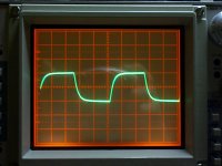
Attached is a square wave at 200KHz - no ringing! Connecting the speaker wires, with or without zobel, doesn't change this square wave behavior. This is with an R2 value of 25 ohms.
- keantoken
The interesting thing about this circuit is that it seems to be immune to capacitive loads, thanks to the special attention made to the compensation. In simulation, stability margin into any capacitive load will be no worse than 20 degrees. So in fact, if this bears out, we may be able to set normal stability margin at less than 90 degrees, since capacitive loading will pull the margin to around 20 degrees no matter what. However this has ramifications for other load types. Voltage drive amps are by nature immune to inductive loading, and usually require very little compensation if an inductive load is all that is expected. Optimally, we hope that the C6 miller cap is all that is required to make the amp stable into inductive loads. However when this is not the case, such as it is for this amp and most others, we must increase other types of compensation.
Inductive stability is very important, since at HF your amp will most likely see an inductive load no matter what, be it speaker cables, headphone cables, etc.
Attached is a square wave at 200KHz - no ringing! Connecting the speaker wires, with or without zobel, doesn't change this square wave behavior. This is with an R2 value of 25 ohms.
- keantoken
Attachments
It's been several days now, and the amp is still going strong. I need to find some audio quality 5p and 2.2pF caps to use for input shunt and phase lead, and then compensation will find it's final values.
- keantoken
- keantoken
Hmm. I wonder if I'm the only one that knows how to adjust the compensation correctly? 😉
It is only through constant trial and error on the simulator that the method has come to light, and the prototype so far has indicated that the simulation is accurate. I only need the parts to experiment further.
Adjustment involves C3, C2, R2, and C6. All of these contribute to the final result. (from the schematic in post 372)
A hint at C3, it is best to be as low as possible, since this will introduce phase shift at lower volumes because of the input volume control impedance.
In the current simulation, OLG bandwidth is -3db@200KHz into 60 ohms.
- keantoken
Last edited:
Wavebourn's recordings, available for free from his site, are by far the most realistic I've heard (though I haven't heard much). Playing through my amp, it sounds as if the speaker has been replaced by the singer's head. The effect is ruined completely with my car amp.
- keantoken
- keantoken
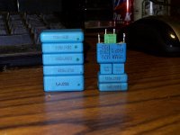
Okay, I just replaced C2 with one of the small 5n6 blocks in the photo below.
The highs are much smoother, much less harshness! Yes, I know I said the harshness was gone already... But there's less of it now, I swear! It looks like I just haven't hit the limit yet.
- keantoken
The highs are much smoother, much less harshness! Yes, I know I said the harshness was gone already... But there's less of it now, I swear! It looks like I just haven't hit the limit yet.
- keantoken
Attachments
Last edited:
- Status
- Not open for further replies.
- Home
- Amplifiers
- Headphone Systems
- Rush Cascode Headphone Amp + JLH Output Stage