Hello everyone.
I've spoken wbold things, things of dreams, things that never happened...
Well this time I did something that actually worked.
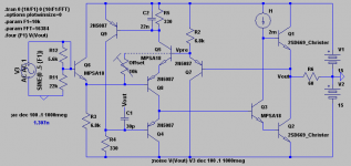
I've always been fascinated with the Rush Cascode. It has interesting characteristics that distinguish it from the LTP, but basically it's the same idea, an inverting and noninverting input. The JLH output stage was chosen because it had the lowest impact on the harmonic signature. This is a class A design.
It was named after Christopher Rush, the one who used it in a NAD preamp some time ago. But the name is misleading, because (trusting the experts here), it's not really a cascode. I've ventured to give it a new name which is more to the point. So I've decided to call it the NTP, standing for "No-tail Pair".
Many experts would have the NTP banned from amplifiers altogether, but this is audio; we're given some slack as long as it sounds good. Sometimes it even sounds better.
The three interesting things about the NTP are:
1: It has a exponential transfer function, as opposed to the LTP which has a parabolic (looks like it anyways) one. This means:
a: It does not cancel even harmonics, which instead balance the odd harmonics. (in the present circuit, odd harmonics are actually canceled to an extent by Q7 and Q6)
b: It can deliver more power on positive strokes. This isn't really that great, because by this time the negative strokes are clipping... It may be better than the alternative though, the LTP, which clips both ways and is thus current limited both ways (and distorts both ways too).
2: It doesn't need a current source like the LTP does; this makes it faster at HF and there is less loss as well. The LTP is not as suited for HF work (I've simulated several HF buffers)
3: You don't need to worry about balancing the transistors! YAY! (well, this could be said to be a bad thing, since in a conventional LTP balance will decrease its distortion)
4: Contrary to popular belief, the NTP is does NOT necessarily produce more distortion than the LTP. Since the NTP is faster, BW is increased, and the OLG BW can be increased, which decreases HF distortion. Or you can go the other way, and increase open-loop gain, which will decrease LF distortion at the expense of relative HF distortion.
The largest hurdle with implementing the NTP has been DC offset; on its own, the rush cascode has 1.2V between its two inputs. This is a serious problem and is hard to correct without being clever. If you manage to do that, temperature drift might or might not be a problem.
The presented solution I don't think can be beat in terms of temperature drift cancelation, offset correction, ease of use and component number. An interesting note is that the buffers Q7 and Q6 even increase speed. Offset can easily be corrected via a single potentiometer.
My reasons for designing this amp were:
1: To design a good amp using the NTP, for others to try out and see whether it works well; to see what the consensus was on its value in audio amplification.
2: To see if using the NTP is practical in real life.
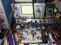
So far I have been blown away. Not that it means much, because my best source has only been my Soundblaster X-fi with Koss Portapro heasphones. But what that DOES mean, it that it's not bad, and better than most consumer equipment in the low-$ range. Unfortunately, my bench is still young and I don't have sophisticated signal sources for measuring distortion, BW... This is where I would like others to try.
The first difference I noticed was between the snares and high frequencies, and brass instruments; they sound more like they are supposed to. I can discern between a clap and a snare. It also sounds much more dynamic. I can discern this through the loud hum; I have a ground loop between my power supply and soundcard source (NOT a design flaw, only a testbench problem). But it sounds good enough that it doesn't really bother me, although eventually it will have to be fixed.
The current design is the one that is on the bench. I had stability problems using MJE340/350 outputs, but I decided I could do better with component choices and went with a few 669A's I had laying around from a computer monitor. So far, there have been no signs of instability.
For low DC offset it is important that Ic for Q7 and Q6 is equal to the Ic of Q5 and Q8. Offset at the moment is 40mV, because I haven't added the adjustment trimmer. To add offset control, place a trimmer resistor between the bases of Q7 and Q8 (you may have to decrease R2 and R3 to give it enough current).
I think many will see C2 and scratch their heads. This is certainly NOT the normal method of stability compensation. So how does it work?
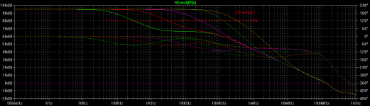
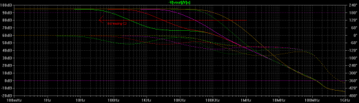
Well, first of all, C2 is dependent on C1. As frequency increases, C1 draws more current, which causes the Vbe modulation of to increase, which causes C2 to suck up more current. This combination allows us to create a quick decline of open-loop bandwidth, rather than a slow one that spans the audio spectrum. So we get less distortion in the 5kHz area. (an attachment shows C2's affect on OLG).
You might also ask why C1 is connected directly to the output instead of Q3's collector, as is standard. Well, it is better this way if you can get away with it, because otherwise strange harmonics from Q1's Vbe will be injected into the feedback loop - this a much worse issue in class AB and B amplifiers, because it adds a lot of transient trash to the feedback loop, causing harshness, brightness, HF distortion... (perhaps the idea of Cdom in itself is not what is harmful to Blameless amplifiers as some say - rather, its implementation could be better?)
So, now that I've got it working, I want others to build it and see for themselves of my own observations matches up. To an extent they come from simulation; so I might not be totally right.
The current source I1 is a standard 2-transistor CCS with a 20 turn trimmer.
I have pictures and the schematic attached.
While visions of sugarplums dance in his head,
- keantoken
I've spoken wbold things, things of dreams, things that never happened...
Well this time I did something that actually worked.
I've always been fascinated with the Rush Cascode. It has interesting characteristics that distinguish it from the LTP, but basically it's the same idea, an inverting and noninverting input. The JLH output stage was chosen because it had the lowest impact on the harmonic signature. This is a class A design.
It was named after Christopher Rush, the one who used it in a NAD preamp some time ago. But the name is misleading, because (trusting the experts here), it's not really a cascode. I've ventured to give it a new name which is more to the point. So I've decided to call it the NTP, standing for "No-tail Pair".
Many experts would have the NTP banned from amplifiers altogether, but this is audio; we're given some slack as long as it sounds good. Sometimes it even sounds better.
The three interesting things about the NTP are:
1: It has a exponential transfer function, as opposed to the LTP which has a parabolic (looks like it anyways) one. This means:
a: It does not cancel even harmonics, which instead balance the odd harmonics. (in the present circuit, odd harmonics are actually canceled to an extent by Q7 and Q6)
b: It can deliver more power on positive strokes. This isn't really that great, because by this time the negative strokes are clipping... It may be better than the alternative though, the LTP, which clips both ways and is thus current limited both ways (and distorts both ways too).
2: It doesn't need a current source like the LTP does; this makes it faster at HF and there is less loss as well. The LTP is not as suited for HF work (I've simulated several HF buffers)
3: You don't need to worry about balancing the transistors! YAY! (well, this could be said to be a bad thing, since in a conventional LTP balance will decrease its distortion)
4: Contrary to popular belief, the NTP is does NOT necessarily produce more distortion than the LTP. Since the NTP is faster, BW is increased, and the OLG BW can be increased, which decreases HF distortion. Or you can go the other way, and increase open-loop gain, which will decrease LF distortion at the expense of relative HF distortion.
The largest hurdle with implementing the NTP has been DC offset; on its own, the rush cascode has 1.2V between its two inputs. This is a serious problem and is hard to correct without being clever. If you manage to do that, temperature drift might or might not be a problem.
The presented solution I don't think can be beat in terms of temperature drift cancelation, offset correction, ease of use and component number. An interesting note is that the buffers Q7 and Q6 even increase speed. Offset can easily be corrected via a single potentiometer.
My reasons for designing this amp were:
1: To design a good amp using the NTP, for others to try out and see whether it works well; to see what the consensus was on its value in audio amplification.
2: To see if using the NTP is practical in real life.
So far I have been blown away. Not that it means much, because my best source has only been my Soundblaster X-fi with Koss Portapro heasphones. But what that DOES mean, it that it's not bad, and better than most consumer equipment in the low-$ range. Unfortunately, my bench is still young and I don't have sophisticated signal sources for measuring distortion, BW... This is where I would like others to try.
The first difference I noticed was between the snares and high frequencies, and brass instruments; they sound more like they are supposed to. I can discern between a clap and a snare. It also sounds much more dynamic. I can discern this through the loud hum; I have a ground loop between my power supply and soundcard source (NOT a design flaw, only a testbench problem). But it sounds good enough that it doesn't really bother me, although eventually it will have to be fixed.
The current design is the one that is on the bench. I had stability problems using MJE340/350 outputs, but I decided I could do better with component choices and went with a few 669A's I had laying around from a computer monitor. So far, there have been no signs of instability.
For low DC offset it is important that Ic for Q7 and Q6 is equal to the Ic of Q5 and Q8. Offset at the moment is 40mV, because I haven't added the adjustment trimmer. To add offset control, place a trimmer resistor between the bases of Q7 and Q8 (you may have to decrease R2 and R3 to give it enough current).
I think many will see C2 and scratch their heads. This is certainly NOT the normal method of stability compensation. So how does it work?
Well, first of all, C2 is dependent on C1. As frequency increases, C1 draws more current, which causes the Vbe modulation of to increase, which causes C2 to suck up more current. This combination allows us to create a quick decline of open-loop bandwidth, rather than a slow one that spans the audio spectrum. So we get less distortion in the 5kHz area. (an attachment shows C2's affect on OLG).
You might also ask why C1 is connected directly to the output instead of Q3's collector, as is standard. Well, it is better this way if you can get away with it, because otherwise strange harmonics from Q1's Vbe will be injected into the feedback loop - this a much worse issue in class AB and B amplifiers, because it adds a lot of transient trash to the feedback loop, causing harshness, brightness, HF distortion... (perhaps the idea of Cdom in itself is not what is harmful to Blameless amplifiers as some say - rather, its implementation could be better?)
So, now that I've got it working, I want others to build it and see for themselves of my own observations matches up. To an extent they come from simulation; so I might not be totally right.
The current source I1 is a standard 2-transistor CCS with a 20 turn trimmer.
I have pictures and the schematic attached.
While visions of sugarplums dance in his head,
- keantoken
Attachments

Last edited:
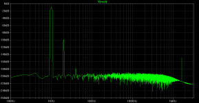
Here is an FFT plot of the output spectrum. Taken at 1KHz, 1V pk-pk.
At higher voltages, 3rd harmonics are canceled. If you want stop this and minimize distortion (which then will be very low, possibly inaudible), you can replace R2 and R3 with Jfet CCS's. As it is, it is kind of my experiment on whether dominant 2nd harmonics sound good as opposed to dominant 3rd harmonics.
Harmonics decrease very quickly after the 2nd and 3rd; this indicates that multiple transfer curves with different parent functions aren't interfering with each other. Instead, the output is a single exponential function, except for the 3rd harmonics which are canceled.
Simulations are made with about 200mA class A bias. Guessing by the heat, I think I've been listening at about 100mA.
The music I used to compare is here. I used the tracks "Nocturne", "Empty Frame feat", and "Heart of Vlad".
http://baddudesmusic.com/symphony.html
Also, I have to clarify. I didn't use the Portapros, I actually used my old in-ear headphones that I modified, which are more detailed. I don't have two amps so I couldn't do stereo, so I connected right and left together, which presents the headphone amp with about a 9 ohm load.
- keantoken
Attachments
Last edited:
Here is an FFT plot of the output spectrum.
At higher voltages, 3rd harmonics are canceled. If you want stop this and minimize distortion (which then will be very low, possibly inaudible), you can replace R2 and R3 with Jfet CCS's. As it is, it is kind of my experiment on whether dominant 2nd harmonics sound good as opposed to dominant 3rd harmonics.
Harmonics decrease very quickly after the 2nd and 3rd; this indicates that multiple transfer curves with different parent functions aren't interfering with each other. Instead, the output is a single exponential function, except for the 3rd harmonics which are canceled.
Simulations are made with about 200mA class A bias. Guessing by the heat, I think I've been listening at about 100mA.
- keantoken
Attachments

Hey keantoken,
In order to make your circuit more understandable, please add the *.acs . Also where is the NTP in your schematic?
In order to make your circuit more understandable, please add the *.acs . Also where is the NTP in your schematic?
Last edited:
Anthony,
It's a very clever circuit, like the use of EFs to level shift!
Keep up the outstanding work,
Hugh
It's a very clever circuit, like the use of EFs to level shift!
Keep up the outstanding work,
Hugh
Last edited:

Thanks guys!
The circuit looks and IS very, very simple, but I have been thinking it over for months and months, exploring many options and I don't think it can be beat in terms of performance vs. part count. (at least for the same topology of design)
- keantoken
The circuit looks and IS very, very simple, but I have been thinking it over for months and months, exploring many options and I don't think it can be beat in terms of performance vs. part count. (at least for the same topology of design)
- keantoken
Thanks guys!
I don't think it can be beat in terms of performance vs. part count.
Contest? 😎
Uh oh, that usually means I'll be the loser. 😀
Also, I'm super slow at the bench, can barely get anything done in a day... I can simulate 300MPH though, and then TRY to build a prototype.
First though we would have to define a criteria for "performance". The chief winning qualities of this amp I believe are:
1: Distortion profile. 3rd harmonics are much lower than 2nd harmonics, and 5th and above are practically nonexistant (according to simulation at least...). THD vs. volume also decreases when you give it gain, so... Not to mention the Jfet CCS mod.
2: HF performance. "knee" point of OLG is above 7k, which means THD is equal over most of the audio range (1k and 10k THD are the same), as opposed to super-opamps, where OLG starts to decrease after 10Hz...
I'm not a fan of suspense, but I'd be happy to see what you have in mind. 🙂
- keantoken
Don't forget about phase intermodulation distortions, and about how distortions change with dynamics. 😉
Don't forget about phase intermodulation distortions, and about how distortions change with dynamics. 😉
True, at positive and negative excursions the balance of Q6 and Q7 changes, which will affect dynamics.
My aim was not necessarily for the lowest numbers. There are improvements that will increase performance, such as replacing R2 and R3 with Jfet CCS's.
More this is an experiment on the affects of dominant 2nd harmonics as opposed to 3rd. Maybe ill-conceived, since I've never listened to much and probably can't tell the difference.
I just smoked my first resistor. I was using a 10 ohm resistor to gauge bias current. I moved the circuit over to my stronger power supply, and turned the bias pot a bit too high... Now I'm using a .22 ohm resistor.
Here are simulator shots of square wave response. The square wave has a risetime of 1nS. The greatest mystery about the square wave test to me is why no one ever specifies the risetime of the square wave they use? It certainly does matter, since any amp will have no trouble at all with a 10u risetime, but might spit chunks of plastic at you if you try to put a 1nS pulse through it. We need a standard here.
The plots show the difference between the positive and negative slew rates. The negative slew rate is worse because with such a fast pulse Q5 actually runs out of juice; no surprise here. It's hardly worth increasing C1 to fix the negative slew rate issue, because it won't help at audio frequencies. A tame positive slew rate is good enough. There is some ringing, but this only shows up at very fast risetimes.
The circuit is neat to explore.
- keantoken.
Attachments

Last edited:
Okay, I couldn't solve the noise problem between the computer and amp but I did the next best thing amd used my portable CD player.
I have never heard anything more awesome. I could hear every detail. Even low level noise (from CD player) was audible within drum beats. Until now I thought my ears just sucked, but it turns out it's not my ears, it's the equipment!
There was no harshness, and some instruments that used to be in the background were brought to the front. I could clearly discern whispers and quiet echoes, and I'm no longer confused over the lyrics of the music I listened to.
The high end sounds much, much better. I think the distorted high end in most equipment causes lots of noise during excursions that destroys low level detail. But with this, I could hear all the details no matter how loud it was.
I'm sure this will be my first amp, but what to call it...
Bias current is about 400mA, cooled by a rather noisy fan (oddly enough, I couldn't hear the fan through the headphones; it didn't interfere with the circuit).
I think I'll try my hand at making a PCB.
C1 and C2 are both ceramics, I was wondering if this is bad.
- keantoken
Last edited:
HI Keantoken,
---I've always been fascinated with the Rush Cascode. It has interesting characteristics that distinguish it from the LTP, but basically it's the same idea, an inverting and noninverting input. [....] It was named after Christopher Rush, the one who used it in a NAD preamp some time ago. But the name is misleading, because (trusting the experts here), it's not really a cascode. I've ventured to give it a new name which is more to the point. So I've decided to call it the NTP, standing for "No-tail Pair".---
You can consider the Long Tail Pair as a parallel differential stage and the Rush circuit as a series differential stage.
You're right Forr, thanks. I was on the verge there but just hadn't realized it was this simple. The two are directly related, only opposites that perform the same function.
This gives rise to some more naming possibilities.
- keantoken
This gives rise to some more naming possibilities.
- keantoken
Hello Anthony
Well done, your first protype are a success and a clever circuit, protobard are neat and easyer than making pcb, DipTrace are usefull for final board.
For real time distortion measuring you can use your sound card and there is many FFT freeware, like SpecLab, Spectran, Realtime Analyzer, etc..
Here is a Word document with two low distortions sinewave generators schematics with texts.
Bye
Gaetan
Attachments
Last edited:
Thanks for the file, Gaetan. It turns out to be just what I was looking for the other day...
Unfortunately I will have to build something sensitive enough to determine the THD of my circuits. I figure I can do this with flying colors (of sparks), but it may take some time.
If I ever need to I plan on building this:
Ultra low distortion audio oszillator the never ending search for a pure sine
Back to this thought...
I'm not sure I want to risk a contest, but if it will get you to show me what you have in mind, I suppose I have to...
- keantoken
Unfortunately I will have to build something sensitive enough to determine the THD of my circuits. I figure I can do this with flying colors (of sparks), but it may take some time.
If I ever need to I plan on building this:
Ultra low distortion audio oszillator the never ending search for a pure sine
Contest? 😎
Back to this thought...
I'm not sure I want to risk a contest, but if it will get you to show me what you have in mind, I suppose I have to...
- keantoken
I was just kidding. You amp is very good, enjoy it!
However, there are many ways to skin the cat... 😉
However, there are many ways to skin the cat... 😉
- Status
- Not open for further replies.
- Home
- Amplifiers
- Headphone Systems
- Rush Cascode Headphone Amp + JLH Output Stage