I will, thanks!
Yes, many roads lead to Rome... But how many options are there that can give low distortion AND even harmonic dominance? Say below .004%THD at normal listening levels.
- keantoken
Yes, many roads lead to Rome... But how many options are there that can give low distortion AND even harmonic dominance? Say below .004%THD at normal listening levels.
- keantoken
Even harmonic dominance means nothing if distortions are too low to hear at all. THD at normal listening levels shows nothing at all.
I don't want to sound like Lumba; I am just too lazy today to discuss it deeper and to show some different options. 😉
I don't want to sound like Lumba; I am just too lazy today to discuss it deeper and to show some different options. 😉
No disagreement here, but at the same time I'm not about to argue about what is audible and what is not. If a certain harmonic profile sounds good at high distortion, then it should not be harmful at low distortion and so I'm in the "safe zone". It becomes more risky when I start thinking about economy over quality and making questionable design decisions which no one can decide on whether they're audible or not. (by all means, if you have a better solution, then cut to the chase! Otherwise, what do you want from me!?)
- keantoken
- keantoken
Member
Joined 2009
Paid Member
Nice work indeed. I've been wondering for sometime when we would see this circuit - one that you have hinted at several times over the past weeks and months.
Your bench set up looks good - like somewhere an engineer has been playing 😀
I also like your philosophy / approach.
Your bench set up looks good - like somewhere an engineer has been playing 😀
I also like your philosophy / approach.
Thank you Bigun.
I know, it's been sooooooo long. I have hundreds of circuits that I'm determined not to post until I at least get them working on bench. 😀
Yes, a very unorganized one though. As soon as I get one thing done I have to dig up my probes, headphones, alligator clips... All over again! but it's worth it, at least for now.
I'm much happier reinventing the wheel and coming from the ground up because when I listen to the gurus talk it's all just confusing and there are some arguments, and I can't hope to tell who's right for myself. But there ARE ways to go about things to avoid arguments, I prefer the "swat fly with buick" approach. No one can complain! 😀
I like the idea of a certain amp having a transfer function of a single parent curve instead of having multiple parent curves - parabolic, exponential, quadratic... All jumbled together. I suspect that the brain is aware of mathematics in its approach to percepting sound.
- keantoken
(by all means, if you have a better solution, then cut to the chase!
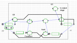
Here is the concept:

Hi kt, quick question. Is your circuit supposed to have 0dB gain? -- because that's how your file simulates. Am I missing something obvious?
Yes Iko, no gain.
For low impedance headphones, it's not necessary. It's also convenient in that you can just put differential probes at the input and output to see the difference and distortion. (good idea, keantoken! I think I'll go do that!)
- keantoken
For low impedance headphones, it's not necessary. It's also convenient in that you can just put differential probes at the input and output to see the difference and distortion. (good idea, keantoken! I think I'll go do that!)
- keantoken
I might give this a try, considering how simple it is and that I got all parts on hand, except for the D669, but might try bd139 instead.
Cool! I can post a version that uses gain, if necessary. Adding gain has implications for the stability compensation.
- keantoken
- keantoken
Okay, cool.
A Cascoded MOSFET with an active push-pull current source. Wavebourn, you've exceeded the 30pF input capacitance criteria! 😀
Also, how do I get around the hum problem? I could give more detailed data if I could connect it to my computer with minimal noise. Any ideas?
- keantoken
A Cascoded MOSFET with an active push-pull current source. Wavebourn, you've exceeded the 30pF input capacitance criteria! 😀
Also, how do I get around the hum problem? I could give more detailed data if I could connect it to my computer with minimal noise. Any ideas?
- keantoken
Well, as I said I hooked up my super sensitive differential scope between the input and output, and the difference at AC is not higher than expected, so I am not sure it's running exactly as intended.
- keantoken
- keantoken
Gah! I meant to edit my last post.
I meant to say that it's running exactly as intended.
- keantoken
I meant to say that it's running exactly as intended.
- keantoken
Okay, cool.
A Cascoded MOSFET with an active push-pull current source. Wavebourn, you've exceeded the 30pF input capacitance criteria! 😀
It is not a cascoded MOSFET. It is a follower loaded on a counter-modulated current source, and powered by another follower controlled by the same signal. As the result, non-linearities caused by modulations of D-S voltage (or C-E voltage) and drain current (or emitter current) are minimized.
JLH output stage you use resembles one part of this my concept, related to constant current only: the lower transistor is a counter-modulated current source. If you want to improve it turn the bottom transistor into a fair current mirror, adding one more transistor and couple of resistors. As is, it has flaws: a first, "dirty" base-collector currents are always summed with driving current adding an error that depends on temperature, and phase distortions are asymmetrical, especially on higher frequencies, and quiescent current goes up with frequency due to rectification of the signal. Also, quiescent current of an output stage is highly modulated by temperature because it depends on beta of the lower transistor. It causes both thermal instability and non-linearity on lower frequencies caused by thermal intermodulations.
Last edited:
The simulator shows only a small increase in bias current, when using Andy_C's 2SC4793 model. 3mA difference between 20 and 30 degrees C. I don't think this is enough to be a problem. Unless the simulator is missing something? In fact, in the two-Q CCS I'm using, output current decreases with temperature, so there is possibly some negative feedback.
As far as phase distortion, the transistors used have very low Cob, and the MPSA18 is buffered through Q4. What affect will it have in the audio spectrum?
I just did a .ac analysis, there is no indication of these problems. Forgive me for using the simulator exclusively, I have no way of measuring this in real life.
- keantoken
Hey keantoken,
Interesting circuit! Do you have any schematics of NADs application?
Did some DC-sims with the circuit in your first post but can not eliminate some DC at the output(in the ballpark of 60mV). The optional DC-comp didn´t work as supposed. Tried both with DC and AC-feedback.
Anyway THD with 20db gain seems very good. But that is probably what one could expect with an open loop gain of ca 66dB.
Will do some sims using a PNP LTP for comparision.
Last edited:
First of all, say you have 2mA bias for the Rush pair.
This means you should have 2mA for the buffers Q7 and Q6.
So if your power supply is +-30V, that's 15V per transistor, which comes to about 6.8k for R3 and R2.
But we need to give some slack here so that we can adjust the offset to be right. So lets lower R2 and R3 to 6.2k, and add in the adjustment resistor.
In the simulation, Offset is below 1mV with about a 6k offset resistor.
If you changed the rail voltages, you will have to adjust R2 and R3 as necessary.
I've been shown schematics of NAD's schematic, but never bothered to save it to hard drive. :/ I keep forgetting I guess.
- keantoken
Last edited:
I used your values of +/-15V. With the schematic(1st post) as is(pure follower) offset is zero. When adding 10k/1k feedback for 20dB gain we get an offset of ca 60mV. Tried with and without a capacitor to ground in series with the 1k.
One problem with this arrangement is that unlike in an LTP, the base current if the differential currents does not cancel.
It should help to use a feedback network of 1k/100 (or even 100/10). This way, Ib won't cause so much offset.
If all else fails, send me the file you use. Maybe there is something wrong.
- keantoken
It should help to use a feedback network of 1k/100 (or even 100/10). This way, Ib won't cause so much offset.
If all else fails, send me the file you use. Maybe there is something wrong.
- keantoken
- Status
- Not open for further replies.
- Home
- Amplifiers
- Headphone Systems
- Rush Cascode Headphone Amp + JLH Output Stage