JLH describes a similar set up method whereby he recommends a pot + cap in the feedback route. Tune the pot to give "best" shape to the test squarewave.ringing is at about 1.43MHz. R2 was at 2.2 ohms, just changed it to 33 ohms and ringing is greatly reduced, at about twice the frequency. I will switch in a 100R trimmer and find the right value this way.
overshoot visible in the squarewave is a visual way of saying the amplifier overamplifies fast transients, but applies the correct amplification to slower signals.adjusting the compensation has had an enormous affect on the sound. ....................
.................. the sharpness of the earlier prototype was emphasizing higher octaves ................
.................... but I only changed compensation, how would LF linearity be affected?)... I am totally weirded out by this, the difference in sound is just uncanny................
In music some of the signals are low frequency and some are mid frequency and some are high frequency.
Many of the mid and treble frequencies are the constituent of the harmonic structure that is a fast transient of a lower frequency. If the amp overamplifies some of these harmonic constituents then the sound that emanates will have an emphasised HF (sharpness) relative to the fundamental of that transient.
test this same amplifier with a non changing sinewave at any frequency in it's pass band and it will show constant amplification.
It's the amplifier's inaccurate transient response that changes the sound. This must be eliminated or minimised for the truth to shine through.
I can confirm that it can be tweaked to make the overshoot small or even eliminate. In simulation at least.
One thing I noticed is that the output transistors have a large impact on the behaviour of this amp. Can you give BD140 or 2SC5171 a try?
One thing I noticed is that the output transistors have a large impact on the behaviour of this amp. Can you give BD140 or 2SC5171 a try?
I only have mysterious 2SC4370's to use. They are similar to the 2SC4793, but the datasheet gives no detailed information.
Andrew, I believe you are right. However, I have to turn the squarewave up to 500KHz before the overshoot is visible (at audio frequencies, it is perfect). My PSP can't be putting out anything higher than 22KHz, and the simulator shows no change in specs at audio frequencies.
The Niceness knob in the first plot is turned all the way off, minimizing distortion. In the second plot, it is rotated to 100 ohms, nearly full on. The Niceness knob adds distortion, that is it's purpose. It is intended to add mostly 2nd and even order harmonics. The axes are labeled correctly.
- keantoken
Parallel a batch of small signal transistors, its only +/-6V into 8 ohms...
0.5625W per polarity, assuming worst dissipation +/-3V 50% square wave.
Two half Watters per rail should be enough. Can secondary breakdown
happen with only 3V (or must always figure against the "full" 6 or 12?)
Did I give you small signal clip-on heatsinks, or is that "2nd box" stuff?
0.5625W per polarity, assuming worst dissipation +/-3V 50% square wave.
Two half Watters per rail should be enough. Can secondary breakdown
happen with only 3V (or must always figure against the "full" 6 or 12?)
Did I give you small signal clip-on heatsinks, or is that "2nd box" stuff?
Last edited:
I like using the outputs I have now, it's simple and no worries about current sharing. I don't know what more there is to gain and whether it will justify the extra complexity and space.
- keantoken
- keantoken
Well, a day has passed and the amp is passing the time test... However the compensation is taking a little longer than expected, because of the effect on the sound. It may take longer to get it just right...
I'm slightly disappointed, the Niceness knob after the compensation changes sounds more like an SQ knob. Turning it up makes the sound worse. :/ I will fiddle with it a little more to make sure I'm not missing something.
This amp sure shines on piano pieces. I'm testing it with a speaker and it's working great... Why not make a power amp version? 😉 For the Betsys I'm using, 2W is good enough, I could upgrade the outputs and increase bias current, and it would be pretty darn perfect for high-efficiency fullrangers...
But of course, that is off in the uncertain future...
- keantoken
Okay, after testing several extremes of compensation values and having them all seem to fall short, it is beginning to seem like there really is a "sweet spot". R2 seems to have the largest affect, I'm not sure if R14 has one. For a 20-turn trimmer the best method I've found is to adjust the trimmer lower until ringing increases, then back it off a turn or two until you can't see the waveform change while turning. Tomorrow I will adjust the trimmer in real-time and see if I can track down this sweet spot, or test my imagination.
- keantoken
- keantoken
I got wheel-spoked heatsinks, for metal can type transistors. At +-6V I don't know if heat is a problem. I could easily bolt the outputs to the chassis and I think that would be enough.
- keantoken
- keantoken
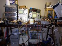
Someone commented about my workstation. I suppose I do have enough equipment to do a few interesting things... Though I would prefer a nicer signal generator. Not many parts to throw together either.
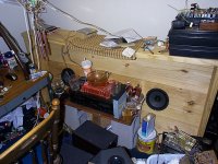
I thought I was obligated to post a decent picture of my workstation head-on, without that ugly speaker in the way. It is currently playing, as can be seen on the scope and DMM, through the right speaker in the second picture.
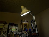
However I think the last picture is what will make you drool...
- keantoken
I thought I was obligated to post a decent picture of my workstation head-on, without that ugly speaker in the way. It is currently playing, as can be seen on the scope and DMM, through the right speaker in the second picture.
However I think the last picture is what will make you drool...
- keantoken
Attachments
Okay, I've had a few lazy days for casual listening.
It sounds better than my car amp for sure. I would prefer it to sound as good as my headphones plugged into the source, but I think that is asking too much. Although it is better in one way: I am consistently impressed with this amp's ability to reproduce music enjoyably. Even with my headphones plugged directly into the source, the highs are better and the sound is clearer, but the emotional impact and involvement is lost. I think the compensation can still be improved, it still has some ways to go.
I haven't yet tested into actual headphones. Using the speaker is much easier and less stressful, I only have one pair of good headphones in the house.
- keantoken
... I would prefer a nicer signal generator...
You can build a very good one yourself with max038 chip. I did it recently and it's really nice. I wrote a thred about it on Serbian forum, so I won't write about it here, but you can see the schematics and wave captures here:
Generator funkcija sa MAX038 chip-om - diyaudio.rs
Hi Juma! I will look into that, it looks simple enough for me. I would use a discrete output buffer rather than opamps because I'll probably try something stupid like running a flyback with it.
- keantoken
- keantoken
That's an idea too, except my sound card oscillates rather badly and I haven't been able to stop it. I don't think I'll ever buy a Creative card again.
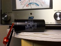
Here's some good pics of the latest addition to my bench.
I think I've narrowed down the best compensation. Cymbals sound nice, and real!
http://kngi.org/talesproject/site/r...dle-Aselia_Biology_(Forest_of_the_Treant).mp3
- keantoken
Here's some good pics of the latest addition to my bench.
I think I've narrowed down the best compensation. Cymbals sound nice, and real!
http://kngi.org/talesproject/site/r...dle-Aselia_Biology_(Forest_of_the_Treant).mp3
- keantoken
Attachments
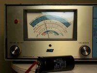
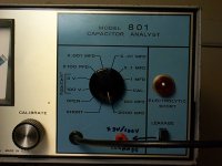
The "effective capacity" reading on the capacitor tester is interesting. Most electrolytics only have an "effective capacity" about half their capacitance value - however, a golden orange NCC 470uF cap from 1979 has an unusually good figure of 400uF. Annoying, since you can't tell the actual value, but useful at the same time.
- keantoken
- keantoken
Attachments

Last edited:
I do believe the change is for the better.
With the smaller feedback cap, bias is much easier to tune (a large feedback cap will magnify small offset changes).
Everything does seem to sound better. Seems to sound more musical, instruments are fuller.
Anyways, although it was an impulsive move, anything could have been better than that 6.3V 3300uF (not 6800u in fact) cap (now 470u, with mylar 1u bypass), and the input cap used to be mylar, polycarbonate can't be a bad move, especially an Ero MKC.
I also removed the Niceness circuitry, it seems to affect stability and as I've discovered, the compensation is crucial for this amp. I may try it again under more controlled circumstances. Anyone wishing to try for themselves shouldn't be worried, compensation is only affect at the very highest extreme setting.
- keantoken
Last edited:
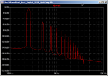
FYI, this is the worst case spectrum driving my current load, the Wild Burro BetsyK. Worst impedance is about 5.4ohms at 250Hz. Even so, it is the best sound I've heard!
PS: all my simulations for a few months have been on Linux. Latest UbuntuStudio, running LTSpice on WINE. It's faster than on windows, which rocks. There is some UI weirdness, but only small things. Linux sounds better too I believe (Ubuntustudio specifically is geared towards multimedia production, including audio - my reasoning for choosing this distribution was it was best suited for audio).
- keantoken
Attachments
- Status
- Not open for further replies.
- Home
- Amplifiers
- Headphone Systems
- Rush Cascode Headphone Amp + JLH Output Stage