
I discovered that a big source of interference was the fluorescent bulbs we're using. They're not much different than plasma globes in the way they work, and in the interference they produce. (they're supposed to last 6 years - what a laugh! We replace them all the time)
- keantoken
- keantoken
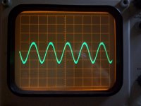
Alright, I've been taking a break sort of, but here are pics from a very basic distortion test. I put one probe of my differential scope plugin to the input and output of the amp, and adjust the volume so they cancel out and leave the distortion residual. These tests are from the version in post 261, I haven't prototyped newer versions yet.
Long story short, it doesn't work so well if there is a lot of phase shift between your amp's input and output. I simulated to find the best point to test, which is about 5KHz with minimal phase shift.
The first trace is 5KHz distortion with no niceness, 20mV/div. The monotonic distortion of the NTP is visible as the slight egg curve. This disappears without the 50 ohm load.
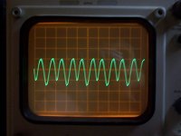
The second trace is the same, with niceness all the way up. 2nd harmonics are obvious. 200mV/div.
Third trace is 15KHz, with niceness turned all the way up, 500mV/div. Without niceness, phase shift is too large to see the distortion.
- keantoken
Long story short, it doesn't work so well if there is a lot of phase shift between your amp's input and output. I simulated to find the best point to test, which is about 5KHz with minimal phase shift.
The first trace is 5KHz distortion with no niceness, 20mV/div. The monotonic distortion of the NTP is visible as the slight egg curve. This disappears without the 50 ohm load.
The second trace is the same, with niceness all the way up. 2nd harmonics are obvious. 200mV/div.
Third trace is 15KHz, with niceness turned all the way up, 500mV/div. Without niceness, phase shift is too large to see the distortion.
- keantoken
Attachments

- intermission -
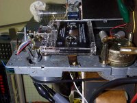
I pulled this out of a really old tape player. I think the tape head is mono. In the future I think I will use my own circuits to make it into a full cassette player. I've cleaned all the parts and oiled them again, tested it on a tape head cleaner/degausser.
I'm listening to it through headphones from my scope's signal output connector.
Bela Fleck and the Flecktones
- keantoken
Attachments

Yes, cassettes are really cheap these days. I scored some really nice ones at 50c a piece. Eh, cassettes aren't audiophile approved, but I couldn't care less.
Hey kt, I got some good news. Got my tube headphone amp working, stable, and with decent distortion (maybe). Can't say anything about the sound, as the prototype is mono only. At this point if you got a stable recipe of your own headphone amp it'd be great, because I'll be busy for the next little while with the pcb and proper build of my amp.
Hey kt, I got some good news. Got my tube headphone amp working, stable, and with decent distortion (maybe). Can't say anything about the sound, as the prototype is mono only. At this point if you got a stable recipe of your own headphone amp it'd be great, because I'll be busy for the next little while with the pcb and proper build of my amp.
There is no reason why this schematic should be unstable, you should be able to get it working with minimal finicking. It's slower, but still very fast.
- keantoken
- keantoken
Attachments
Last edited:
How did Q9 sneak back in?
Oops. 😉
I've tested that circuit, and it goes to 160KHZ at full output voltage without problems. I think it's fine, Ken. Distortion is now very low, as are higher order distortions. Personally I would like to revert to this version, despite the extra component. I'm sure it's well worth it.
- keantoken
Last edited:
kt, are you around? I wonder if you ran a pulse source of about 20kHz through your circuit, in simulation at least. Something like this: PULSE(0 500m 0 4u 4u 25u 50u)?
Edit: I should rephrase. Are you using in your prototype 2sc4793 at the output?
Edit: I should rephrase. Are you using in your prototype 2sc4793 at the output?
The rigged tape player sounds awesome, and happens to be the perfect volume plugged directly into the input of my headphone amp. Thing is incredibly noisy though, output voltage is around 1mV.
There is this constant 30KHz interference coming from somewhere, I don't know where. It's driving me crazy.
- keantoken
There is this constant 30KHz interference coming from somewhere, I don't know where. It's driving me crazy.
- keantoken
OK, I hope to find the time tomorrow to give it another try. I'll build your circuit exactly as shown and will let you know how it goes. Is there any point in trying to increase the idle current in the output stage? If so, what would be the best way to do it?
These days you can find really nice tape decks in places like Goodwill. I got myself at least five of them, some for parts... they can have the nicest analog vu-meters 😀
These days you can find really nice tape decks in places like Goodwill. I got myself at least five of them, some for parts... they can have the nicest analog vu-meters 😀
I have a Technics RS-TR252 tape deck, don't know if it's any good but I've heard many good things about Technics products.
IIRC, it is better to increase Q12 bias current than it is to increase OP quiescent. The reason is that Q1's Vbe no longer plays part in the thing. If quiescent is increased too much, the Ib transfer will slope downward and then fight with the opposite transfer of the NTP, canceling some even harmonics.
Try halving R23 and R21 and see what happens to the spectrum.
- keantoken
I tried doubling the output current, which decreased high order harmonics. So foot is firmly in mouth. Still, I want to avoid components getting warm.
- keantoken
- keantoken
What changes have you made?I tried doubling the output current, which decreased high order harmonics.
Still, I want to avoid components getting warm.
Why? 🙂 You can always use it to warm up your coffee.
That's a good idea Iko, a class A amp to warm up your coffee at the office!
I simply changed R16 and R20 to 1.8 ohms.
- keantoken
I simply changed R16 and R20 to 1.8 ohms.
- keantoken
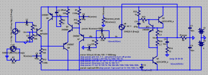
Okay, I'm screwing around with the prototype again.
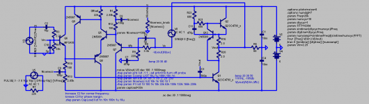
I haven't had any design ideas for months, so I can freeze the schematic below, except for the compensation values, which should be determined when and if I ever get a PCB design ready.
I've been looking at square response lately, and have some observations:
1: heatsink should be grounded.
2: input pot must be grounded.
3: Don't leave the third lead hanging on the bias trimmer.
Before fixing these I had strange problems where it would oscillate near the middle of the volume setting. Now square wave response is much smoother, with a little ringing.
- keantoken
Attachments
Last edited:
I realize R1 and R13 are weird values, that was an experiment. These should be 2.7k.
- keantoken
- keantoken
The amp is very good about producing very fast sounds like drums and especially synthetic clicks/pops in some electronic tracks. And I suspect the sound, even though it's coming from 1 speaker, is a little more 3D. Echoes seem to sound more real. This makes scary noises much more convincing.
I managed to connect it to one of my main speakers that I'm used to, it should be okay since I've been abusing this circuit with 4 ohm speakers for some time with no failures. The sound is much cleaner at the high end, the bass somewhat truer I think, but it's subtle. This amp sounds very good with electronic music. instruments are easy to follow. Bass seems more controlled, more like a bump and less like a dull thump, and doesn't interrupt other instruments.
Listening to a violin piece, the violin didn't sound harsh like it used to. I am surprised that an amp could change the sound of a violin that much. Not sure what to think.
I'm comparing it to a consumer quality car amp, the Sony Xplod mx-502Z. My 100mA class A headphone amp has better bass than this 250W amp!
- keantoken
- Status
- Not open for further replies.
- Home
- Amplifiers
- Headphone Systems
- Rush Cascode Headphone Amp + JLH Output Stage