Okay, comparing with my better speakers is more revealing...
With my old amp the highs were harsh and fatiguing. I fixed this by adding a 25 ohms series resistor. It worked, but the speaker itself worked sub-optimally. I use BetsyK's from Wild Burro Audio.
With this amp I can remove the series resistor and all is well, despite the 5 ohm dip at 250Hz.
The "niceness" has an interesting effect. Too little and the sound is cold, too much and the sound is veiled. The sound is okay either way, but somewhere in the middle is "just right". This effect doesn't stand out for any certain part if the music, which seems to indicate making the effect independent of input loading was a good decision.
I'm thinking of adding another effect knob... heheheheheheh
- keantoken
Dude, when you gonna bust out them +/-24V supplies and
give the neighbors something to really complain about?
give the neighbors something to really complain about?
I've been waiting to do anything big until I know I have all the parts, and can lay out matching parts for stereo builds.
Now that you mention it though, the neighbors actually gave me that 250W car amp. They thought it was broken, but when I tested it everything was perfectly fine. So I think one of my projects will be to return the favor and give them something of proportionate value, but far superior engineering... I have an idea for a super-powerful BJT amp, capable of super-high power peaks... (wait, that's backwards isn't it? They'll be driving me crazy with the bass...)
I worry about stacking the switchers, is there a way to sync the pulses? If not, there will be a heterodyne effect. I don't think interference is a big problem though?
- keantoken
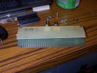
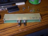
Alright, my next prototype will be stereo and I think I will be able to fit it in the attached space. Used to be some module for some arcane device? Got it from a repair shop and though it would be perfect for prototyping.
If/whenever I get that done, after tests I might send it off in an envelope to inquiring minds, to see how much my ears correlate to everyone else's.
Bonus: a rare look inside keantoken laboratories.
- keantoken
If/whenever I get that done, after tests I might send it off in an envelope to inquiring minds, to see how much my ears correlate to everyone else's.
Bonus: a rare look inside keantoken laboratories.
- keantoken
Attachments

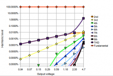
Here is a harmonic profile vs. output voltage graph for a 33 ohm load, lowest load for +-5V swing, which is close enough to clipping to increase THD. Listening with headphones is usually done at around +-50mV (for my portapros at least). This done with the Niceness knob at 1kohm.
- keantoken
- keantoken
Attachments
Last edited:
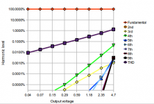
Here is with the niceness knob at 100 ohms. The 2nd harmonic is hidden behind the THD line, since the other harmonics are so low there is hardly a difference between the two.
- keantoken
- keantoken
Attachments
Last edited:
Yes, it still has a little ringing but it's stable.
Without sophisticated equipment I can't get the perfect -90 degree OLUG phase, but I can tweak for minimal ringing and stability.
- keantoken
Without sophisticated equipment I can't get the perfect -90 degree OLUG phase, but I can tweak for minimal ringing and stability.
- keantoken
Sync +/- stacked switchers, else hetrodyne? What???
Barely almost not quite qualifies for imaginary problem.
Stop making stuff up! Sides, what caps is for.
Current sharing across paralleled switches might be
example of an actual problem if you wanted one.
Barely almost not quite qualifies for imaginary problem.
Stop making stuff up! Sides, what caps is for.
Current sharing across paralleled switches might be
example of an actual problem if you wanted one.
Last edited:
It would be nice to lower the ringing; how do you plan on doing that?
Is it necessarily worth bothering with?
I mean, if the resonance is up around 80kHz, why bother?
se
I don't follow your comparison with the previous post.Here is with the niceness knob at 100 ohms. The 2nd harmonic is hidden behind the THD line, since the other harmonics are so low there is hardly a difference between the two.
Are the left hand scales labeled correctly?
Last edited:
Is it necessarily worth bothering with?
I mean, if the resonance is up around 80kHz, why bother?
se
So my pet bat can listen to her favourite recordings 🙂
On a more serious note I didn't think it necessary, that's why I said it'd be nice. The main cause for ringing seems to be the C2, R2 pair; but removing them might affect stability.
The resonance is higher than 80KHz as I recall. Remember, I am aiming for ultrasonic linearity! Iko, I think your bat will like it as much as a bat can appreciate SS.
Ringing and overshoot are essentially the same thing as I understand, except overshoot is only visible for half a cycle. Turn up the square wave enough and you'll see a few cycles form.
My compensation isn't so great for inductive loads, but voltage drive amps are (as far as stability is concerned) immune to inductive loads. This compensation reacts mostly to output current, so it is more effective with capacitive loading where voltage drive naturally has troubles, especially with the common VAS miller cap compensation; this cap only reacts to a change in output voltage, so if the output voltage doesn't change, as is the case with a capacitive load, the amp is reverted back to full open loop stability as if there were no compensation.
The values of C2 and C5 are set I think, I think I will be able to quell the ringing by changing R2 and R14. If not, increasing C6 should help (current value is 10pF for lack of a 5p cap), however I want to keep 100KHz phase shift as low as possible.
AndrewT, the harmonics are plotted as a percentage of the fundamental. Note that the left axis is logarithmic. The 2nd harmonics comprise almost the entire THD reading, which is why the 2nd harmonic percentage and the THD percentage are right on top of each other.
Steve, you may be right, I'll be seeing soon.
- keantoken
Alright, ringing is at about 1.43MHz. R2 was at 2.2 ohms, just changed it to 33 ohms and ringing is greatly reduced, at about twice the frequency. I will switch in a 100R trimmer and find the right value this way.
- keantoken
- keantoken
47 ohms for R2 works best currently, which is close to the simulator predicted 51 ohms.
- keantoken
- keantoken
Okay, adjusting the compensation has had an enormous affect on the sound. Before, drums and fast noises were very powerful. This time, not so and everything seems to sound a lot more organic.
I think the instruments are more blended, either that or the sharpness of the earlier prototype was emphasizing higher octaves and segregating instruments with fascist fervor.
It sounds much less cold, much much warmer, except where the detail has gone. I'm not sure where, but I think it is the lower midrange where the effect was strongest (this would be the place of lowest impedance for the speaker, but I only changed compensation, how would LF linearity be affected?)... I am totally weirded out by this, the difference in sound is just uncanny.
Let me put my foot in my mouth for a second though. It's been raining and I wonder if the barometric pressure isn't having an effect... The difference in sound is so surprising, maybe i should wait a day and see if I make the same observations.
The circuit is stable with a 33nF film cap on output. Not bad for an amp with an OLG bandwidth of 100KHz, right? I haven't tested with larger caps.
I seem to have traded sharpness and detail for a more organic sound. I will test a different way to set the compensation.
- keantoken
Okay, I've asked my brother in a few times to confirm my own hearing, and he has (without suggestion) agreed with all my own observations.
The ratio of R2 to R14 has a very large effect on the sound. If R2 is large and R14 is small, the sound will be highly organic, but veiled, and less detailed. If
R14 is larger and R2 smaller, the sound will be less organic, colder, but more detailed and sharper, with powerful drums. This goes with user preference, but I prefer somewhere in between, but not too cold. What disturbs me is that this has more effect than the Niceness knob ever did!
My preference thus far is for R2 to be 9.2 ohms, with maybe the zobel gone altogether (used 100 ohm series as an experiment, and it sounded good).
Edit: I realize I contradicted myself. I say my preference is not too cold, yet I set R2 to 9.2 ohms. I'm still working out the details...
- keantoken
Last edited:
Okay, here's more detailed info:
I first had R2 set to 2.2 ohms, and R14 set to 10 ohms. This produced post #300.
I then set R2 and R14 both to ~45 ohms, and this produced post #317.
I then experimented with different extremes of both values.
My theory at this moment is that R2 determines the sharpness vs. warmness quality of the sound, and that low values of R14 are bad. If this is true, consider the following:
Stability is a function of the loading of the input stage at the OLUG frequency. Both R2 and R14 compensations contribute to this. If R2 is high, R2 must be low to produce the same loading and vice versa. The difference is that the loading coming from R14 loads the output stage as well as the input stage.
It is really starting to sound brilliant I think...
- keantoken
is this confirming that the scales are labeled correctly?AndrewT, the harmonics are plotted as a percentage of the fundamental. Note that the left axis is logarithmic. The 2nd harmonics comprise almost the entire THD reading, which is why the 2nd harmonic percentage and the THD percentage are right on top of each other.
Look at the absolute values of each of the harmonics in the two cases.
The second posting shows very clearly that some of the harmonics are approaching a factor of 10 higher than the previous posting.
That does not equate with your statement
since the other harmonics are so low (there is hardly a difference between the two)
With the niceness knob turned to your example value, some of the higher harmonics are much worse than without the tuned value niceness knob.
- Status
- Not open for further replies.
- Home
- Amplifiers
- Headphone Systems
- Rush Cascode Headphone Amp + JLH Output Stage