Alright, I finally realized I'm being held to a higher standard.
I get it, guys. Took some time, but don't get cocky, because I have to return the favor and blow your socks off. Fine! I'll give you exactly what you want!!!
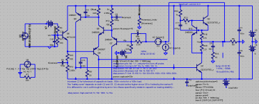
Here it is, in all it's glory.
I want to return focus to post #214. Look at those awful Vbe curves and what they do to the higher order distortions! I have thus come to the conclusion that the B-E resistor is a cruel and unusual way to treat an amp and the person who must listen to it.
Funny thing is, see how many transistors I wasted just trying to buffer it? Doesn't matter, it distorts just the same and even worse when all the Vbe's add up and are imposed across R4, and the current gain is only about 2!!!
To make things worse, Vbe is highly nonlinear, which injects distortions right into the feedback loop and everything. Nasty!!!
Distortion is actually less, after removing both buffering transistors and the resistor. Since Hfe is far more linear than Vbe, we've just beheaded most higher order distortions. Performance into 4 ohms is clean!
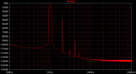
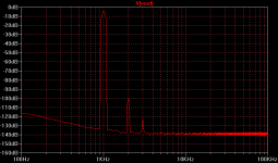
Attached is the FFT at 1KHz, 2Vpk-pk into 60 ohms. The first plot is with the Niceness knob turned all the way up, the second with it all the way down. In addition, the simpler circuitry has improved speed, which means smaller compensation. The OLG corner has moved to 100KHz!
Are you happy now!? Iko, I know you're smiling! The old HeadRush is back!!!
(Looks awfully "Tube-like", no?)
- keantoken
I get it, guys. Took some time, but don't get cocky, because I have to return the favor and blow your socks off. Fine! I'll give you exactly what you want!!!
Here it is, in all it's glory.
I want to return focus to post #214. Look at those awful Vbe curves and what they do to the higher order distortions! I have thus come to the conclusion that the B-E resistor is a cruel and unusual way to treat an amp and the person who must listen to it.
Funny thing is, see how many transistors I wasted just trying to buffer it? Doesn't matter, it distorts just the same and even worse when all the Vbe's add up and are imposed across R4, and the current gain is only about 2!!!
To make things worse, Vbe is highly nonlinear, which injects distortions right into the feedback loop and everything. Nasty!!!
Distortion is actually less, after removing both buffering transistors and the resistor. Since Hfe is far more linear than Vbe, we've just beheaded most higher order distortions. Performance into 4 ohms is clean!
Attached is the FFT at 1KHz, 2Vpk-pk into 60 ohms. The first plot is with the Niceness knob turned all the way up, the second with it all the way down. In addition, the simpler circuitry has improved speed, which means smaller compensation. The OLG corner has moved to 100KHz!
Are you happy now!? Iko, I know you're smiling! The old HeadRush is back!!!
(Looks awfully "Tube-like", no?)
- keantoken
Attachments

Last edited:
Yes kt, I'm smiling! I haven't kept up with exactly all the versions, but that original one I liked much, at least the way it simulated. So if this one is closer to that one, I like that. The distortion profile of this one is nice, for sure. How far are you from a prototype?
Prototyping this one will not be hard, since I can just clip components off of my old prototype. I may have to change the compensation.
- keantoken
- keantoken
The first one simulated so well because the MPSA18 models were a match made in heaven.
But, I think your original idea to adjust R1 to balance the transistors will work to achieve the same performance if it is desired. It may interfere with the offset control, however I should probably use an output cap or servo for a headphone amp anyways.
- keantoken
But, I think your original idea to adjust R1 to balance the transistors will work to achieve the same performance if it is desired. It may interfere with the offset control, however I should probably use an output cap or servo for a headphone amp anyways.
- keantoken
I'm sure you'll find a nice solution for offset control. A simple servo might just work without too much adverse effects. But if it isn't really necessary, why bother.
If I use a series cap, I want to DC bias it for best operation, which would necessitate input circuitry that references ground to the same rail.
With a feedback capacitor, offset is pretty stable. If you don't want an output cap or a servo, then you will want a regulated supply, because the air conditioner turning on and off bumps the offset up or down a few mV.
- keantoken
With a feedback capacitor, offset is pretty stable. If you don't want an output cap or a servo, then you will want a regulated supply, because the air conditioner turning on and off bumps the offset up or down a few mV.
- keantoken
Member
Joined 2009
Paid Member
Wow, this looks like it has the promise of being THE headphone amplifier. I will be awaiting to hear about how it sounds, how it measures and how robust it is.
Prototype is running...
And I do think it sounds much better! Seems to sound a lot more full-bodied. Sounds very mature, doesn't give the impressions of flawed reproduction. But that's just with 30 seconds of listening, and with distorted guitar+saw synths type music.
- keantoken
And I do think it sounds much better! Seems to sound a lot more full-bodied. Sounds very mature, doesn't give the impressions of flawed reproduction. But that's just with 30 seconds of listening, and with distorted guitar+saw synths type music.
- keantoken
It's getting more amazing. I can turn up the volume without my ears hurting (is that good? Or bad... 😀)! I'm getting that kinda creepy feeling...
I got the impression at first that it has slightly less resolution, but I'm not sure again, since some things seem to sound more clear. Was harshness giving the impression of clarity? This is pretty clear, and has much less fatigue than it's last incarnation, if any.
- keantoken
I got the impression at first that it has slightly less resolution, but I'm not sure again, since some things seem to sound more clear. Was harshness giving the impression of clarity? This is pretty clear, and has much less fatigue than it's last incarnation, if any.
- keantoken
I just had my brother test it out.
His observations correlate with mine. He didn't mention fatigue, and I notice he didn't use the volume control much. This was strange, considering he's obsessed with preserving his hearing and is afraid of loud music. He said that all the detail of sharp, fast noises was preserved.
He had something interesting to say about the Niceness knob. He said that with it turned up, the music sounds "more". He agreed to using the adjective "fuller". He said with it turned down the music sounded more hollow.
- keantoken
I've got a 10Lb 40H choke...
Just kidding, cause I'm keeping it.
Then again, prolly so does that
junk scope...
But you need two that match.
Woud it matter if they were both
wound on the same core?
Just kidding, cause I'm keeping it.
Then again, prolly so does that
junk scope...
But you need two that match.
Woud it matter if they were both
wound on the same core?
Last edited:
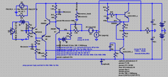
re old headrush...
Q9, C13, R5 redundundunundant. Get rid...
Move ROffset 220, and C2 33n, to Q8C.
And drive Q1 from here instead.
Q9, C13, R5 redundundunundant. Get rid...
Move ROffset 220, and C2 33n, to Q8C.
And drive Q1 from here instead.
I might do as you say, but I would not put Roffset in that position, because of the Vbe distortion I mentioned.
Q9 is not redundant, it increases OLG and decreases distortion. I might still get rid of it, but then it won't be so easy to control offset.
Chokes? For what?
- keantoken
Q9 is not redundant, it increases OLG and decreases distortion. I might still get rid of it, but then it won't be so easy to control offset.
Chokes? For what?
- keantoken
Last edited:
allison ccs, not fer serious dude...
I could give beans about offset,
you'll still need 220 across Q1BE
for Q5 Q8 quiescent.
I could give beans about offset,
you'll still need 220 across Q1BE
for Q5 Q8 quiescent.
Last edited:
0.66VBE/220R=3mA,
feedback loop will do the rest...
Constant current do-nothing.
But keeps other transistors on.
You already have this at VBE Q9,
don't get rid when you ditch Q9.
just move down to Q8C, VBE Q1.
feedback loop will do the rest...
Constant current do-nothing.
But keeps other transistors on.
You already have this at VBE Q9,
don't get rid when you ditch Q9.
just move down to Q8C, VBE Q1.
Last edited:
Ken, your solution works better at near-max output WRT high order harmonics. I think I will end up using it. I thought Q9 would buffer any fell Vbe effects, but it simply mirrors in it's own Vbe what would have happened if Q1 had a B-E resistor.
Perhaps I could try some quirky cascode thingy to fully isolate the Vbe. Oh horrors!
- keantoken
Perhaps I could try some quirky cascode thingy to fully isolate the Vbe. Oh horrors!
- keantoken
Here is the circuit I'm looking at in the sim.
THD@1KHz into 60 ohms 2V pk-pk, is .0083%. Larger than I hoped, but others here should be satisfied. With the current design, no one should worry about high-order harmonics. I have done my absolute best, save for removing the level shifters, to ensure as little high order trash as possible.
Every revision since the first prototype seems to have improved sound, except for minor compensation changes. There are a few other things I still want to address.
The circuit no longer reproduces ultrasonics with the same grace it does the midrange, due to the vastly reduced open-loop gain. Distortion increases steadily with frequency. I'm not sure how this will affect the sonics, and in this regard previous versions might be more favorable.
Phase shift at 100KHz is -2.4 degrees.
Upper -3db point is at 3.5MHz. Lower -3db point is determined by input and feedback caps.
It is stable beyond slew and current limit into capacitive loads.
Bonsai!
- keantoken
Attachments
I haven't built this new version.
What's interesting about the latest revisions is that it doesn't sound harsh or seem to distort no matter how loud you crank it. When you turn up the volume it doesn't sound any different - just louder! The first prototypes exhibited this but not so fully.
One of the reasons I don't like reducing OLG is that this causes odd harmonics to increase. We can swamp out odds with evens, but I have to agree with Iko's interest in leaving odds out entirely. This may be a case where less OLG is actually worse. But we shall see.
- keantoken
Last edited:
Hi kt, it's almost impossible to read some of the values off the schematic. What's v6? If I may suggest, when you post the schematic to remove the grid so the grid dots may not be mistaken for decimal values. Also, would help to have the distance between components large enough that their info doesn't overlap.
- Status
- Not open for further replies.
- Home
- Amplifiers
- Headphone Systems
- Rush Cascode Headphone Amp + JLH Output Stage