Hi Carlos, thanks for the photos and your progress report.
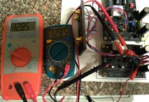
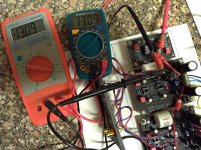
Generally mounting the boards like that in the open is OK for testing. I would take advantage of the easy access to measure the voltages at various points in the circuit.
Troubleshooting is much more rapid if, in addition to knowing that no sound comes from a channel, or a hiss from the other, you know for certain that the correct power supply voltages are reaching the op amps.
I am wondering about how much voltage imbalance is acceptable? I have 0.46VDC difference on the input side with a true dual mono set-up. 26.16 vs 25.70 are the actual measurements. That is without the ICs in place.
Should I add a dropping resistor and if so, what wattage would be safe?
Should I add a dropping resistor and if so, what wattage would be safe?
I assume you mean 26.16 V and 25.70 V from V+ to V- on the left and right channels? It's no issue at all, and expected given the circuit design. The trim resistor tunes the V+ and V- to be equal to each other on each channel, so the op amps are powered by symmetric voltages.
Yes, exactly. I have the rails balanced within a tenth of a volt but the two channels are just under 0.5V different. Sounds just fine but I was wondering if I should try and get them closer.
There will always be some difference. A little bit more here than normal for "regulated" power supplies because I'm not using a precision reference. Instead, I'm using the Vbe diode drop of the transistors, which vary from part to part. Anything less than 1 V is nothing to worry about. Higher than that, you can try swapping Q7 or Q8 between channels, or, the final solution, use sets of Q7,Q8 with measured Vbe chosen to total up (Q7 Vbe + Q8 QVbe) to the same value.
Thanks Richard. Emerald is singing nicely already. I did use low noise resistors in the R1-R5 positions as well as the switchboard as I had almost all of the values in stock. Wired the signal path in silver solid core 24g. wire (well from the jacks in and out at least. An Obbligato Premium cap 2.2uf for final coupling. Sounds fantastic already!
You seem to be all set. The audio cap and low noise resistors ice the cake as it were.
Happy listening!
Happy listening!
I'd forgotten about this. 2 box build with switches for mc/ mm, high low gain, and between 47k and plug in loading.
emerald phono | Flickr
emerald phono | Flickr
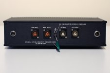
For the record, I would have recommended that the GND post be connected to the Emerald chassis and the GND terminal of the Emerald boards.
The GND terminal of the Emerald boards connects internally to the COM terminals, which connect back to the "zero V" of the PSU. The GND of the boards is by definition the quietest part of the circuit, though they are all at the same nominal zero potential of course.
Which was determined to be the better connection?
I don't see why you'd want to change from through hole to SMD, it seems to me you gain nothing for the trouble, but thanks for sharing your mods to the forum.
You should be able to get a faster turnaround than 3 months. pcbway is a good place to small quantities of boards made.
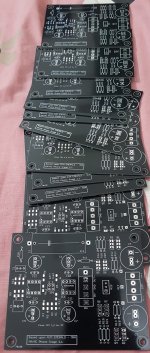
Dear Richard got the boards, minimum order was for 10 boards. I needed only four.
I am giving up rest of the six boards as I don't need them, these are not up for sale as I don't need money and don't want to make gains on your project.
If you need them let me know, talk offline/PM please. I cannot send to many people so if you don't need them I'll take your recommendation on whom to send them to with only one condition that if anyone other than you gets them they are not to be sold or used for any commercial gains.
I'm not a regular on the board so I will manage to send them once you decide something.
Best
MRA
Attachments
Thanks for making these available to readers of diyaudio.
If anyone is up for soldering SMT resistors, the boards @rehanabid is offering are otherwise identical to the usual Emerald layout - it's just a slight edit of the Eagle files -so by all means feel free to take him up on the offer.
If anyone is up for soldering SMT resistors, the boards @rehanabid is offering are otherwise identical to the usual Emerald layout - it's just a slight edit of the Eagle files -so by all means feel free to take him up on the offer.
Rma, I'd love to take a pair, and cover any cost to uk and a donation to a charity of your choice
Rma, I'd love to take a pair, and cover any cost to uk and a donation to a charity of your choice
My initials are MRA. Your offer to donate to charity seems attractive, you don't need to cover any cost for shipment its a gift from me, all you have to do is ship two boards (through royal mail) to the gentleman from Italy and send some donation to a charity hope that evens it up.
Next time I'll throw in few "Bugle 2 PCBs" and few others that I have made during the lockdown period. I'll put them up along the projects on my blog may be next week.
I'll send all six boards to you. Right now I am in another city will be back home next Friday till that time please share your full name/address and I'll make the package to deliver through snail mail. Package from "The stylus Lady" was deliver exactly on the 7th day through Royal Mail.
Mra, sorry for the name error. I buy from Hayley all the time, she's the best source of small value close tolerance polystyrene caps in the UK.
I'll pm you my address, happy to forward to Italy. Geoturbo send me your address and I'll forward them onwards.
I'll pm you my address, happy to forward to Italy. Geoturbo send me your address and I'll forward them onwards.
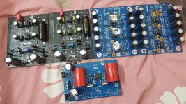
Emerald SMD version both channels almost ready side by side with Bugle 2 (PCB designed from ground up by myself) and an LME49720+BUF634 buffer may be to be used as Headphone amp.
Attachments

Last edited:
Lovely work here on all the Emeralds. Mine has been playing away for months now, and sounds just divine. Very happy camper - thanks again Richard for making these available.
Hello all
And after walking "banging my head against the wall" I found a bad connection of AC to one of the transformers and the reason for the hiss in one of the channels.... The RCA cable I used, despite the multimeter saying that it is being a good electrical conductor, does not connect one of the channels....
My fault, I was the one who set it up.... It's new, it was made on purpose to be premiered with Emerald.
After all this, Emerald is there playing quietly without the slightest hint of noise or hiss.
Thank you Richard and my apologies for this troubled start of yet another Emerald.
Best regards.
Carlos
And after walking "banging my head against the wall"
I found a bad connection of AC to one of the transformers and the reason for the hiss in one of the channels.... The RCA cable I used, despite the multimeter saying that it is being a good electrical conductor, does not connect one of the channels....My fault, I was the one who set it up.... It's new, it was made on purpose to be premiered with Emerald.
After all this, Emerald is there playing quietly without the slightest hint of noise or hiss.
Thank you Richard and my apologies for this troubled start of yet another Emerald.
Best regards.
Carlos
Attachments

- Home
- Source & Line
- Analogue Source
- RJM Audio Emerald Phono Stage Help Desk