Mine is really good now .stuck a couple of blackgate f for supply and it's great
V5i burson for ic1 is also a good option.200 hrs later it's good
Thanks Richard
V5i burson for ic1 is also a good option.200 hrs later it's good
Thanks Richard
I am planning my second Emerald. Wondering if there is any value in using low noise resistors in all or certain locations on the boards?
@Carlthess40. I'm planning to build another emerald and will be happy to sell you mine when the second is done. If you're interested PM me and I'll send some pics.
Ty
Ty
I am planning my second Emerald. Wondering if there is any value in using low noise resistors in all or certain locations on the boards?
Only R1-5 need to be considered, and of those the only ones I'd be concerned about are R2 and R3.
Note that there is little difference in the noise of a regular resistor and a "low noise" resistor, since most of the noise is thermal and fixed by the value of the resistor and its temperature, not the type. And further note that the circuit noise in the Emerald is limited by the op amp used for IC1, rather than any resistance.
More loading and gain options using toggle or switch
Also additional filter cap 4 and 7 pin.
For the former, those are available by adding the Switchboard.
For the latter, there are already two capacitors per IC per rail, why do you want three?
Note that there is very little board area, and the board size and general layout will not change. Only small adjustments are feasible I'm afraid.
/R
Any thoughts about making the boards mirror each other? Be really nice to wire up cleanly.
Also, anyone have a picture as how they soldered in that cap across R5?
Also, anyone have a picture as how they soldered in that cap across R5?
I haven't seen a photo, if it was me I'd solder the cap to the wire leads of R5 sticking out from the underside of the board.
I'm finally getting around to sourcing the components for this phono stage, after purchasing the boards more than a year ago. One thing is puzzling me: Looking at the simplistic drawing for the PSU in the construction guide, a .25A fuse is shown - but on the Emerald Phono stage page, a 1A fuse is mentioned in the PSU section. Which rating is sufficient?
Ultimately you need to make that call. It depends on the AC voltage and the transformer inrush currents, and on whether you use a fast or slow fuse.
I recommend slow, T fuse, 250 or 500mA. 1A is also ok.
I recommend slow, T fuse, 250 or 500mA. 1A is also ok.
Thanks. We're on 230V here. I will opt for a slow-blow. I'm more or less spec'ing as pr. your BOM, except for the caps.
G'Day everybody.
Made it to page 24, but now my eyes are tired.
A simple question to which i did not find an answer: what MC cartridge DC resistance range would be best suited for the 100R load resistor R2? Alternatively, what different values of R2 might you recommend for MC carts well below or above that range?
Would like to have MM and MC inputs and a load switch for MC if it makes any sense.
Thank you for your help.
You are absolutely right, thank you. What speaks against it now is that it will take at least one month to get here., and that i would like it accessible from the outside
However, it gives me the values i was looking for so i can start figuring out the switches.
However, it gives me the values i was looking for so i can start figuring out the switches.
Hi Richard,
I built my first Emerald. I am trying to adjust the internal voltage (V+, V-) with R22. On one of the boards I am getting a reading of 12.92V centered. However, on the other board I am unable to bring the reading below 16.96V centered. What am I doing wrong?
Thanks
I built my first Emerald. I am trying to adjust the internal voltage (V+, V-) with R22. On one of the boards I am getting a reading of 12.92V centered. However, on the other board I am unable to bring the reading below 16.96V centered. What am I doing wrong?
Thanks
Something is wired incorrectly on one board, somewhere in the S-reg part of the circuit. A bad connection, mistaken resistor value, or mixed up (or damaged) transistor.
@enterk 's problem (post 335) turned out to be an instructive case, so I'll explain it here.
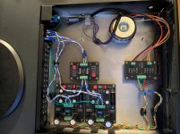
It's a textbook build, two emerald boards share a spacious (recycled) case with a single power transformer, DBRB, and switchboard. All nice and neatly put together. Nothing suspect. Normally these kinds of builds work perfectly from the outset.
The symptoms were just plain weird. Inconsistent and unusual voltages in the power supply, strange whine or rumbling noises on the output, lower than expected signal.
In this kind of situation, you should normally target the power supply. Once verifying that the regulator circuit is functional, that leaves the transformer, diodes, and connections.
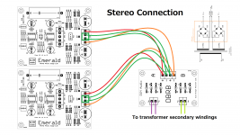
Here I need to break and explain a little bit about the DBRB board. It does the job of two bridge rectifiers, holding 8 individual diodes in two independent and identical groups of 4 (A, D1-4, and B, D5-8). Key point is "independent". To keep general purpose functionality, I do not wire the bridge rectifiers together internally, and the diode connections (~~+ -) and (~~+ -) are electrically isolated. When used with any of my boards the "-" of bridge A and the "+" of bridge B are normally both connected to the circuit common. This is indicated (somewhat confusingly, I now see) by drawing a white box around the outputs and writing "com" next to the box. That was meant to stand in for me saying "Please connect these two to the two COM pads on the Emerald/VSPS/Phonoclone/Sapphire boards"
It did not mean "These two pads are connected together internally", even though on the Emerald boards etc., two pads enclosed in a white box means exactly that. i.e. the two COM pads are literally just two pads connecting to the circuit common (ground).
The difference is critical. On the Emerald you can use both or either COM pad as you like, it makes no difference. On the DBRB, you have to ensure that both pads are wired together somehow. You can jumper across at the board and take a single wire back to one of the COM pads on the Emerald (&c) or, as I had intended, you can run two wires, one from each pad, back to the two COM pads on the boards, where they join up anyway.
It's a textbook build, two emerald boards share a spacious (recycled) case with a single power transformer, DBRB, and switchboard. All nice and neatly put together. Nothing suspect. Normally these kinds of builds work perfectly from the outset.
The symptoms were just plain weird. Inconsistent and unusual voltages in the power supply, strange whine or rumbling noises on the output, lower than expected signal.
In this kind of situation, you should normally target the power supply. Once verifying that the regulator circuit is functional, that leaves the transformer, diodes, and connections.
Here I need to break and explain a little bit about the DBRB board. It does the job of two bridge rectifiers, holding 8 individual diodes in two independent and identical groups of 4 (A, D1-4, and B, D5-8). Key point is "independent". To keep general purpose functionality, I do not wire the bridge rectifiers together internally, and the diode connections (~~+ -) and (~~+ -) are electrically isolated. When used with any of my boards the "-" of bridge A and the "+" of bridge B are normally both connected to the circuit common. This is indicated (somewhat confusingly, I now see) by drawing a white box around the outputs and writing "com" next to the box. That was meant to stand in for me saying "Please connect these two to the two COM pads on the Emerald/VSPS/Phonoclone/Sapphire boards"
It did not mean "These two pads are connected together internally", even though on the Emerald boards etc., two pads enclosed in a white box means exactly that. i.e. the two COM pads are literally just two pads connecting to the circuit common (ground).
The difference is critical. On the Emerald you can use both or either COM pad as you like, it makes no difference. On the DBRB, you have to ensure that both pads are wired together somehow. You can jumper across at the board and take a single wire back to one of the COM pads on the Emerald (&c) or, as I had intended, you can run two wires, one from each pad, back to the two COM pads on the boards, where they join up anyway.
Attachments
Last edited:
I may have asked this before and if so, forgive me. Can I attach a LED to one if the boards without negative effects? I'd probably tie in at the V++ and common before the regulator/filter portion. I'll be using a 6V LED with a dropping resistor.
I'm going to side with the pragmatists and say yes, you can connect an LED with no negative effects.
If possible, string it between V++ and V-- with a current limiting resistor in series.
If possible, string it between V++ and V-- with a current limiting resistor in series.
Hello all
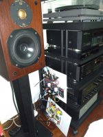
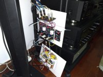
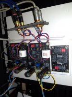
After an extended period of time, I managed to finish the first phase of assembling the emerald boards.
They are connected in double mono mode and the switchboard board is currently off to be connected when it is the final assembly in the chosen chassis.
The first connection attempt did not go very well, the place where I put the plate with the assembly is not the most suitable (obviously), there was no sound from one channel or else there was a high-pitched hiss, from the other channel the sound did not have the volume expected ....
Where did I read a post recently regarding symptoms similar to these ???
The most important was the assembly of the plates, now it is to discover the mistake I made somewhere and then the final assembly on the chosen chassis.
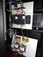
Here, too, I had a doubt to solve, a chassis or two? And after having solved myself for two chassis, another question, identical or of different dimensions? I have decided, the chassis of the power supply narrow and deep, the one of the plates wide and less deep.
Now that I have made the first presentation and if you want to make a comment or ask any questions feel free.
Now I have to try to solve the problems of the emerald and the Pass pré BA-3 which now seems to be well on its way (a bad welding discovered by pure chance).
Best regards.
Carlos
After an extended period of time, I managed to finish the first phase of assembling the emerald boards.
They are connected in double mono mode and the switchboard board is currently off to be connected when it is the final assembly in the chosen chassis.
The first connection attempt did not go very well, the place where I put the plate with the assembly is not the most suitable (obviously), there was no sound from one channel or else there was a high-pitched hiss, from the other channel the sound did not have the volume expected ....
Where did I read a post recently regarding symptoms similar to these ???
The most important was the assembly of the plates, now it is to discover the mistake I made somewhere and then the final assembly on the chosen chassis.
Here, too, I had a doubt to solve, a chassis or two? And after having solved myself for two chassis, another question, identical or of different dimensions? I have decided, the chassis of the power supply narrow and deep, the one of the plates wide and less deep.
Now that I have made the first presentation and if you want to make a comment or ask any questions feel free.
Now I have to try to solve the problems of the emerald and the Pass pré BA-3 which now seems to be well on its way (a bad welding discovered by pure chance).
Best regards.
Carlos
Attachments
- Home
- Source & Line
- Analogue Source
- RJM Audio Emerald Phono Stage Help Desk