In addition
Rim I have a couple of regulated supply s I built for Wayne’s line stage I have on I can use to send 12+ and 12- .
Building an improved adjustable Bi-Polar Power Supply! (Updated: 14th Aug 2020) – audiosy.net
But that should not be needed?
Rim I have a couple of regulated supply s I built for Wayne’s line stage I have on I can use to send 12+ and 12- .
Building an improved adjustable Bi-Polar Power Supply! (Updated: 14th Aug 2020) – audiosy.net
But that should not be needed?
Right, so that tells us the S-reg circuit is not working. Some of the transistors were installed incorrectly, most likely mounted the wrong way around, possibly BD335 swapped for BD336. It's not a fault as both boards are the same, it should be an installation error.
Not that it explains the low gain exactly, but it's a clear place to start.
EDIT: from the photos you posted earlier, it looks like both Q6 and Q7 are flipped 180 degrees.
Not that it explains the low gain exactly, but it's a clear place to start.
EDIT: from the photos you posted earlier, it looks like both Q6 and Q7 are flipped 180 degrees.
Last edited:
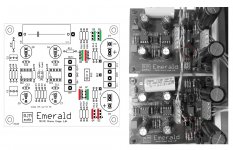
This diagram may help you to troubleshoot.
Looks to me that while Q5,8 are correct, you have Q6,7 flipped.
You are correct I fixed both 6 and 7 and now I get good voltage measurements on both boards, I should have know not to build both at the same time. You have eagle eye, I looked at that darn thing over and over. getting old I guess.
Gain is better, the sound is still poor, the bass is not any where near the bass I get from the Parasound phono stage, the highs are tinny as well.
Is it possible I have damaged the IC's. I don't have any more opa27. I have stock of opa2134, NE5532 orTL072 I could try, suggestions. And again Thank you for the help.
The voltage on board 1 ic1
1;12.4 8;12.5
2; 0 7; 13.04
3;0 6; 0
4; -13.05 5; 0
IC2
1; 12.4 8; 12.4
2;0 7; 13.04
3;0 6; -0.1
4; -13.04 5; 0
The voltage on Board 2 IC1
1;12.2 8;12.2
2;0 7;12.7
3;0 6;0
4;-12.7 5;0
IC2
1;12.2 8;12.2
2;0 7;12.7
3;0 6;-.13
4;-12.7 5; 0
Pin 1 and 8 are unconnected to anything, don't worry about that.
Pin 7 should be about 13 V, pin 4 should be about -13 V ... those look fine so we can conclude the S-Reg is working properly. Pin 6 of IC1 should be almost zero, and a small offset is expected on IC2, as you have.
So it seems to me the electronics is all on point. Weak bass response could indicate an error in the RIAA circuit (C1, C2, R6-9), error of R1 (smaller than expected) or some problem with the configuration of the output coupling capacitor C3. Let's say R11 and R2 were switched by mistake, so R11 was 100 ohms and R2 (which are aren't using) ends up 100k.
success
Richard, with your eagle eye and your guidance I got it working its sounding pretty darn good now. 100r in R11 instead of 100k stupid mistake, times two.
I have to thank you for your help again. Now I will let it play and see how it goes.
Thanks again for the help. Nice work. One piece I think would help is to get the BOM in line with the schematic, the values are different in places. Not a big deal but with some things they can get confusing since many of us don't do this everyday. But all in all good work with the boards and the design.
No hum no noise, all good.
Thank you !
re. BOM, sorry about the confusion there.
If you look at the Worksheet you'll notice the schematic matches configuration A, while the default shipping BOM was changed after the initial introduction to configuration B. Only R3, R4 are different.
If you look at the Worksheet you'll notice the schematic matches configuration A, while the default shipping BOM was changed after the initial introduction to configuration B. Only R3, R4 are different.
Thank you for the reply, Yes I see that I also notice transistors values are different than bom. No worries just an observation all working. I may change the output cap to tighten up the bass response but other than that it’s working fine. Some where in this thread it was stated to let it burn in for a time to tighten it up is that true? And is that something you recommend!
It's not a recommendation, just an observation that the sound changes quite a bit during the first 100 h power is applied.
fyw BD135,137 and 139 are the same part, ditto BD136,138,140. Only the voltage rating is different so I consider them interchangeable.
fyw BD135,137 and 139 are the same part, ditto BD136,138,140. Only the voltage rating is different so I consider them interchangeable.
I was trying to design by myself an op-amp based phono stage, reading some TI application notes. Then I found this simple and interesting project which is inspiring me a lot. I was wondering, have you @RJM ever tried to remove C3 using the technique you can see in SNAA046A, page 4 (bottom)?. If I'm not wrong, this servo amp low pass filters the output signal (extracts DC...), then it supplies with this output the inverting input of the last stage, in order to get 0V at the output. Isn't?
Is there anyone building these and maybe would sell one ? Please message me with a price. I’ve been trying to do some Soldering and my hands are not what they used to be. As I have severe arthritis and carpal tunnel syndrome. My hands just are not sturdy nor can I hold onto the iron for more than two or three minutes at a time without going into a lot of pain. So if someone would help me out that would be wonderful. I also am in the states, in Florida
Did you ever find someone to build these for you? I'm in UK so it would be a bit of a round trip postage wise but if you can't find anyone else...
Did you ever find someone to build these for you? I'm in UK so it would be a bit of a round trip postage wise but if you can't find anyone else...
You might be interested in Keith's "Audiowize" products, which use the VSPS and Emerald boards.
I was trying to design by myself an op-amp based phono stage, reading some TI application notes. Then I found this simple and interesting project which is inspiring me a lot. I was wondering, have you @RJM ever tried to remove C3 using the technique you can see in SNAA046A, page 4 (bottom)?. If I'm not wrong, this servo amp low pass filters the output signal (extracts DC...), then it supplies with this output the inverting input of the last stage, in order to get 0V at the output. Isn't?
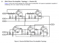
The power supply is very similar to the X-reg, then there's a classic passive pre )U1, U2) with a DC servo (U3) on the back to replace the output coupling capacitor.
Of course a coupling capacitor is simpler and more reliable. For me, the capacitor - while you can hear it - doesn't impair the sound so it's not worth the effort to remove.
Attachments
Not yet
I’ll message you and see what can be done
Thanks
I found the boards very easy to build and I'm no expert (far from it). I'm more than happy to do the soldering for you and ship back, but there must be a US based source of pre built boards?
My brother suffers from similar aliments and I know how painful they are. I'd be happy to help.
The power supply is very similar to the X-reg, then there's a classic passive pre )U1, U2) with a DC servo (U3) on the back to replace the output coupling capacitor.
Of course a coupling capacitor is simpler and more reliable. For me, the capacitor - while you can hear it - doesn't impair the sound so it's not worth the effort to remove.
I got it. I knew it is a different approach amplifier, anyway thank you for your opinion on the decoupling technique 🙂 .
I like yours the most since for me simpler is better.
I will try to put one together soon.
Hey Folks!
With Richard's help I'm updating my PC3 to an Emerald build - going to reuse the same chassis and PSU that I built up back in 2015. One doubt/question I've got - the original PSU I built up as dual-mono and used a 6-pin XLR to run as an umbilical to the boards. Now that I'm digging back in I can't help but wonder if the system would prefer 2x 3-pin runs. It would be easy enough to reconfigure, would just requre tapping a second hold for the additional receptacle and a bit of expense on parts.
Thoughts?
I'm going to order more board stock and was contemplating doing a re-spin (version change) if there are any points to address or additional features to add.
A couple of things come to mind:
An optional capacitor across R5 as discussed some while ago, it might improve high frequency stability.
An optional capacitor across the inputs of IC1. I'm still getting reports of occasional RFI interference issues, this might help tame it - on edge cases at least.
A couple of things come to mind:
An optional capacitor across R5 as discussed some while ago, it might improve high frequency stability.
An optional capacitor across the inputs of IC1. I'm still getting reports of occasional RFI interference issues, this might help tame it - on edge cases at least.
- Home
- Source & Line
- Analogue Source
- RJM Audio Emerald Phono Stage Help Desk