No, it does not. Whether the circuit is powered with 13 V or 14 V or 12 V makes no difference*. There is no "correct" voltage.
* There is a small change, due to variations in bias current and distortion, but op amps are designed such that those variations with supply voltage are extremely small.
* There is a small change, due to variations in bias current and distortion, but op amps are designed such that those variations with supply voltage are extremely small.
As your project is open source I decided to modify the schematics and PCB with a view that many of the resistor values are not available and atleast two resistors are required to get the desired value, secondly I wanted to avoid through hole resistors at the phono stage thus used the SMD 1206 types.
Attached is the modified project, hopefully will be ordering the PCB manufacturer for a minimum of 10 boards, jlcpcb or any other, considering the worldwide shipping problems I am looking at a timeline of atleast 3 months.
All the required components are already in transit and I am keeping my fingers crossed.
Any suggestions about the boards are highly appreciated.
Attachments
I don't see why you'd want to change from through hole to SMD, it seems to me you gain nothing for the trouble, but thanks for sharing your mods to the forum.
You should be able to get a faster turnaround than 3 months. pcbway is a good place to small quantities of boards made.
You should be able to get a faster turnaround than 3 months. pcbway is a good place to small quantities of boards made.
During COVID 19 WFH times, I had too much of free time at hand so decided to reboot old hobbies, been away from diyaudio for almost a decade, resurrected/overhauled/restored old equipment from gran father era like Garrard 401, my first audio player as a kid (Sanyo DXT 5420) and my dads old Technics SL1200.
When I finally got them working again I opened up my AMPs like Denon PMA-880R, Technics Integra A-817-RX and couple of others I was disappointed to see 4558/4560 used in the phono stage and filters, although I replaced them with AD8620/LME49720HA/and a couple MUSE the change was phenomenal.
Then I purchased Fidelity UA-10 in a working condition, but there was hum problem with it that is when I decided to reboot old hobbies and start making DIY projects again, your "emerald" came up in a google search so decided to give it a try.
As for going SMD, a tenant of my commercial property went bankrupt and left equipment one of them is H351 an SMD soldering robot that's why I went the SMD way and besides its good to check waters before jumping in.
My circuits have always preferred an SMD solution for resistors and recently capacitors earlier it was the old soldering station, etc but now I can automate.
Finally finished my build. It became quite complicated with XLR output, switchable ADC for SPDIF output and eleborate power supply for all sections. With shorted inputs the preamp is dead silent on my system (even with my ear in the speaker 🙂), so basically no detectable noise being added by the phono preamp.
In choosing parts i finally settled on an Audyn Plus cap for C3. Just very neutral at a normal price. The opamps took some more experimenting using an album i know by heart (Rumours - Fleetwood Mac) to find my preference using opamps i had in my parts box:
- opa27's on both positions: very neutral, flat response, nothing special but good, i could live with these, just fine
- opa627 on both positions: not neutral, bass heavier, engaging big sound, great for old rock music
- opa134 on both positions: flat to neutral, lighter sounding, detailed but missing punch/drive on some tracks
- LM49710 on both positions: neutral, very detailed, somewhat recessed midrange/vocals
- opa627 on IC1 and LM49710 on IC2: very neutral, dense and powerful sound, fun without fatigue, perfect for me 🙂
The differences are very very small and only detectable for me by using A-B method with a second Emerald Phono from a friend with same power supply etc.. So i completely agree that the opa27 is a great place to start and maybe stay but it was a fun afternoon!
Also tried the R5 bypass with a styro cap of 10pF, really didn't matter much but i let them in there..
Attachments

I'm glad you were able to get all the different boards and power supplies working together with the Emerald. In truth I haven't done much testing on that topic.
Thanks also for your impressions with the op amps. I know a lot of people are interested in knowing how different op amps sound. FYI your remarks on the OPA27, LM49710 and OPA134 are in line with my own observations, though I have not tried the OPA627.
Thanks also for your impressions with the op amps. I know a lot of people are interested in knowing how different op amps sound. FYI your remarks on the OPA27, LM49710 and OPA134 are in line with my own observations, though I have not tried the OPA627.
Has anyone tried using step up transformers with the Emerald for MC carts rather than the higher gain active circuit?
That's certainly do-able, same as it is with any MM stage. It would be an interesting comparison since the Emerald is a MC photo stage that is de-tuned for MM use, rather than an MM stage with a booster for MC.
2020 Xmas sale
From now until the end of the year, all Emerald board orders will ship with a free set of Sapphire 4.1 boards.
(I have some of the older Sapphire boards left over.)
From now until the end of the year, all Emerald board orders will ship with a free set of Sapphire 4.1 boards.
(I have some of the older Sapphire boards left over.)
Ic2 I tried lme49710 happy with it. Similar impressions.
Ic1 could not get a genuine opa 627 so I gave burson v5i a go . It have more grunt and weight .better saturation and separation as well. It sounded quite awful initially but gave it 200 hours burn in . Bass is fast punchy but not round .low is very good . Certainly very entertaining sound.
Opa27 is a neutral choice I find it exceptionally helpful when setting the cartridge .very easy to detect what's doesn't sound right . It's transparent in that sense
I didn't play with the op amp rolling so just a very rough impression
Good morning, I have built the Emerald Phone stage, all working properly from a voltage standpoint. I have a Ortofon 2M Red the sound I am getting is poor I set the emerald up on the BOM default, the output is low gain, and very poor response. Suggestions on the proper set up , this is a MM cart, and the jumpers are not instaled.
@Misterwinefine
I would normally suspect a mistake with a resistor value. Either two resistors were switched around, or one resistor is the wrong value.
The Ortofon is a standard MM cart and should work fine with the default MM settings on the Emerald.
If your hunch is right and the RIAA is wrong as well as the gain problem, I would pay particular attention to R6-9.
R
Checked values
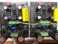
I checked all the values of the those resistors all are correct checked all the values of all the components look correct, sent a pic. Double checked the value of the voltages have +16.50 and -16.48 on the from reference points,
All op amps are getting voltage, sound is there but no bass and it is still a gain issue with output.
With .1v from a signal generator to scope good clean sine wave, on both channels. but when connected to line inputs on Parasound preamp poor quality sound along with no real bass response.
@Misterwinefine
I would normally suspect a mistake with a resistor value. Either two resistors were switched around, or one resistor is the wrong value.
The Ortofon is a standard MM cart and should work fine with the default MM settings on the Emerald.
If your hunch is right and the RIAA is wrong as well as the gain problem, I would pay particular attention to R6-9.
R
I checked all the values of the those resistors all are correct checked all the values of all the components look correct, sent a pic. Double checked the value of the voltages have +16.50 and -16.48 on the from reference points,
All op amps are getting voltage, sound is there but no bass and it is still a gain issue with output.
With .1v from a signal generator to scope good clean sine wave, on both channels. but when connected to line inputs on Parasound preamp poor quality sound along with no real bass response.
Attachments
Last edited:
Ok, there is a few other things we can check.
- input impedance of the Parasound preamp?
- actual voltage into the op amps?
- DC output offset voltage in the output of IC2
Nothing seems amiss from the photo. Please email or pm me for further troubleshooting.
- input impedance of the Parasound preamp?
- actual voltage into the op amps?
- DC output offset voltage in the output of IC2
Nothing seems amiss from the photo. Please email or pm me for further troubleshooting.
Ok, there is a few other things we can check.
- input impedance of the Parasound preamp?
- actual voltage into the op amps?
- DC output offset voltage in the output of IC2
Nothing seems amiss from the photo. Please email or pm me for further troubleshooting.
Thank you for the reply so quick, greatly appreciated. Not sure how to measure DC offset on the IC can you give me direction on that.
IC2
1 :16.2 8:16.2
2: 0 7: 16.7
3: 0 6:-0.11
4:-16.8 5:0
IC1
1: 16.2 8:16.2
2:0 7:16.8
3:0 6:0
4:-16.7 5:0
This is exactly the same on both boards. the Reference Voltage is v+16.80 and the V- is -16.804
The Model 2100 Parasound I am using one of the line input connections not the phono input which it has.
Input Impedance
30k ohms
Output Impedance
< 60 ohms
Input Sensitivity
250 mV for 1 V output
Total Gain: 12 db
Maximum Output: 6.5 V
The power supply voltages are too high. They should be closer to 12-13 V, tops. What is the voltage on the power supply terminals going into the boards, V++ and V--?
The power supply voltages are too high. They should be closer to 12-13 V, tops. What is the voltage on the power supply terminals going into the boards, V++ and V--?
Interesting there at +17.1 and -17.1 from the bridges to the board input. These are running from a 12 volt train the suggested one from the bom and all the parts are from mouser the suggested part numbers.
- Home
- Source & Line
- Analogue Source
- RJM Audio Emerald Phono Stage Help Desk