I think it's obvious to everyone that the waveforms in post #2 are supposed to look different.
It's nice to see what such waveforms look like in real life, though. If you were to use a Dirac impulse as a theoretical model for a click, you would conclude that the + 1 term makes a non-inverting active RIAA stage infinitely more prone to overload, while with the waveforms of post #2, the + 1 term actually doesn't make much of a difference.
It's nice to see what such waveforms look like in real life, though. If you were to use a Dirac impulse as a theoretical model for a click, you would conclude that the + 1 term makes a non-inverting active RIAA stage infinitely more prone to overload, while with the waveforms of post #2, the + 1 term actually doesn't make much of a difference.
Last edited:

Yes phono cartridge is NOT a source of Dirac impulses.
Can you tell us what the good and bad circuits are? Someone else might be able to dig up the circuits.No, sorry, I don't have the circuits.
I have borrowed a network from Bonsai 😉

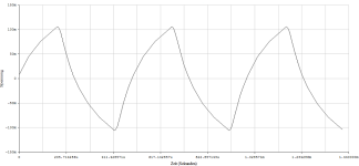
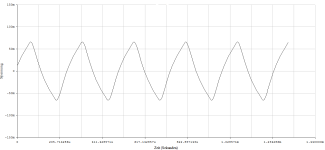
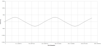
To be able to compare with and without the "+1 error". The MM system is again taken into account as a separate low-pass filter. A direct comparison with the postings #120,21,22 is immediately possible.
To be able to compare with and without the "+1 error". The MM system is again taken into account as a separate low-pass filter. A direct comparison with the postings #120,21,22 is immediately possible.
Attachments
-
 1kHz_Overload_+1Error.png31.6 KB · Views: 32
 -
 2kHz_Overload_+1Error.png34.4 KB · Views: 29
 -
 4kHz_Overload_+1Error.png29.4 KB · Views: 32
 -
 8kHz_Overload_+1Error.png24.4 KB · Views: 27
 -
 16kHz_Overload_+1Error.png23.5 KB · Views: 34
 -
 transition_6kHz_2Vp_Impuls_Folge_+1_Error.png23.5 KB · Views: 28
 -
 transition_16kHz_Overload_+1_Error.png25.5 KB · Views: 36
 -
 transition_8kHz_Overload_+1_Error.png24.9 KB · Views: 37
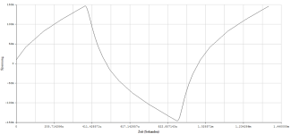
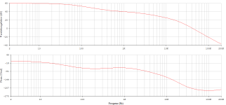
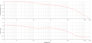
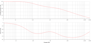
I'll quickly add the transfer function as a picture.
All non-inverting with the classic NE5534 and the original Signetics model. Can we now identify significant differences with regard to the + 1 error ???
All non-inverting with the classic NE5534 and the original Signetics model. Can we now identify significant differences with regard to the + 1 error ???
Attachments
👍while with the waveforms of post #2, the + 1 term actually doesn't make much of a difference.
Correct, but who threw in this side blow?
#
Does anyone think of intermodulation and its products when he or she speaks of signal processing artifacts?
HBt.
If we had two representatives, i.e. typical, of the camps at hand, then we could examine the subjective bad DUT and the subjective good DUT.
We bombard both with low-pass (n=2) filtered impulse sequences and compare the respective responses spectrally.
"Very simple box",
in parallel we perform two or multi-tone tests. Why? Because the bandwidth is limited to 1/(2*PI*75µs).
HBt.
We bombard both with low-pass (n=2) filtered impulse sequences and compare the respective responses spectrally.
"Very simple box",
in parallel we perform two or multi-tone tests. Why? Because the bandwidth is limited to 1/(2*PI*75µs).
HBt.
hbtaudio, can you explain a little more about what you are showing here and in #121 & 122 ?To be able to compare with and without the "+1 error". The MM system is again taken into account as a separate low-pass filter. A direct comparison with the postings #120,21,22 is immediately possible.
Are you feeding a 1Vpp squarewave into the RIAA preamps ? Or is it 2Vpp (+-1Vp) ?
What are the 'Transition' waveforms?
I've actually used selective overload and post filtering to get nice sounding results in another application so I'm open to the possibility 'passive RIAA' may give better audible results with careful choice of overload levels / gain structure / EQ structure.
This requires VERY careful optimisation to sound 'better'. But the results are easily seen on THD or even just looking at waveforms. It was probably the most successful implementation of my Powered Integrated Super Sub technology.
If 'passive RIAA' bla bla gives better audible results, I expect this to be easily visible and measurable too.
I think it's obvious to everyone that the waveforms in post #2 are supposed to look different.
I have just made as precise measurement as I can of the "real" worst case click I was able to get from a vinyl record. Technics SL-1200MK2 turntable was used, with Ortofon 2m Blue cartridge. The signal from the cartridge was immediately amplified with 30dB linear gain amplifier, built around fast AD829 op-amp, the amp has 47k input impedance. To check the amp, below is the step response (140ns rise time, 50MHz sampling) and also a record of 1MHz sine wave (100MHz sampling):


Now, the measured (amplified) click, with 6.25MHz sampling, looks like this:
Its peak amplitude is 50.6mV peak. Without any question the impulse is "slow" (even the fall rate is slow) and reprents absolutely no problem of saturation of a normally designed phono preamplifier. For those who disagree, show me your real measurements, well documented and scaled, to begin a discussion based on facts.
The impulse behind the cartridge cannot be faster than the RLC nature of the cartridge and laws of physics would allow for. There are no mysteries.
Talking about spectrum, it is definitely NOT wide and falls quickly above 10kHz.

Last edited:
Does anyone think of intermodulation and its products when he or she speaks of signal processing artifacts?
HBt.
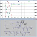
This is what was referred to in #154, varying ground currents, possibly interfering with and corrupting the signal gnd.
The circuit below, that I used to compare the response from the one opamp with active Riaa EQ version versus a three opamp version with passive Riaa EQ, shows the ground current caused by differing supply currents to the input opamps during the input pulse.
In Red the 70mV/100usec input pulse is shown
Blue shows the ground current caused by the differing +/-supply for the one opamp solution.
Green is the ground current to the first opamp taken in the same way.
As can be seen, the one opamp version may be causing more disruption to the audio signal as the passive solution.
In the simulation there is no feedback between signal ground and supply current, but in real life this may result in a longer disruption at the amp's output.
Hans
Attachments
Last edited:
I'm in a bit of a hurry, but I'd still love to ...can you explain a little more about what you are showing (...)
a)
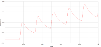
The first case should illustrate posting #118 and the simple laws. In other words, to make it clear that no infinitely large impulses can be given by clicks or pops, i.e. statements claiming that there are large voltage strokes (also in the further consequence) are not correct. It should make the working behavior of the “filter chain” more visible than descriptive words alone could.
We could also express all this with differential equations, but I wanted to get to the heart of the formation /shaping and inevitable signal attenuation.
My concern is the independent recognition of a situation, in this case I wanted to clarify a picture of what the linear signal amplifying modules actually have to process.
I hope you'll forgive me for knowing that reality can never be accurately depicted with this kind of methodical and didactic approach. But as soon as questions arise, the goal has already been achieved and a certain kind of analytical thinking and sensitization is recognizable. So it's a gain all along the line.
In short, the first graphs should invalidate the frivolous / lightly stated and usual statements and comments. Means "ohne Reflektion".
b)
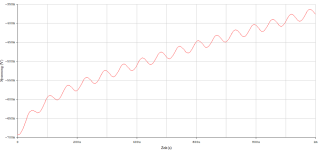
The subsequent postings now process (virtually real, i.e. in a simulation) exactly the inherently resulting temporal signals. Here, however, with the so-called +1 error, i.e. it would now be possible, if there were fundamental changes in the signal processing, to also recognize the part [Zf(jOmega) + Zn(jOmega) ] / Zn(jOmega). However, we see absolutely no significant difference in the time behavior; on the contrary, the well-known charging and discharging behavior of capacitive energy storage devices becomes clear.
Transient analysis not transition, so the difference between a steady state and not "eingeschwungen".
Sorry for the (triggered) confusion,
I hope, as a non-native speaker, I have now been able to express myself more clearly.
greetings,
HBt.
I'm in a bit of a hurry, but I'd still love to ...
a)
The first case should illustrate posting #118 and the simple laws. In other words, to make it clear that no infinitely large impulses can be given by clicks or pops, i.e. statements claiming that there are large voltage strokes (also in the further consequence) are not correct. It should make the working behavior of the “filter chain” more visible than descriptive words alone could.
We could also express all this with differential equations, but I wanted to get to the heart of the formation /shaping and inevitable signal attenuation.
My concern is the independent recognition of a situation, in this case I wanted to clarify a picture of what the linear signal amplifying modules actually have to process.
I hope you'll forgive me for knowing that reality can never be accurately depicted with this kind of methodical and didactic approach. But as soon as questions arise, the goal has already been achieved and a certain kind of analytical thinking and sensitization is recognizable. So it's a gain all along the line.
In short, the first graphs should invalidate the frivolous / lightly stated and usual statements and comments. Means "ohne Reflektion".
b)
The subsequent postings now process (virtually real, i.e. in a simulation) exactly the inherently resulting temporal signals. Here, however, with the so-called +1 error, i.e. it would now be possible, if there were fundamental changes in the signal processing, to also recognize the part [Zf(jOmega) + Zn(jOmega) ] / Zn(jOmega). However, we see absolutely no significant difference in the time behavior; on the contrary, the well-known charging and discharging behavior of capacitive energy storage devices becomes clear.
Transient analysis not transition, so the difference between a steady state and not "eingeschwungen".
Sorry for the (triggered) confusion,
I hope, as a non-native speaker, I have now been able to express myself more clearly.
greetings,
HBt.
With all respect, no kidding but I have no clue what you are telling.
Is it:
1) that +1 for a single amp solution has no impact on the frequency response in the audio range at least when meeting enough gain, then I fully agree, or is it
2) that overload can’t happen, then I also agree, although I thought this was already concluded several times, or
3) has it to do with pops and clicks without overloading for which a simple analysis may be inadequate
Hans
Dear Hans P.
Since all three points apply, it only shows that the chosen form of communication and interaction is clearly limited. That in direct, personal contact between two people and a whiteboard - there will be no misunderstandings. Assuming eye contact, IQ and openness.
Perhaps it is generally helpful to view contributions as a kind of friendly (and hopefully constructive) brainstorming session.
It’s important to point out here that the passive post filter in an all-active RIAA is placed at typically 100-200 kHz. This deals with the opamp zero and pulls in the response in the top octave of the audio band to within 0.1dB. See Lipshitz for details.Regarding click reproduction and overload, a passive post filter won't prevent the amplifier from clipping, as it is placed after the amplifier. It only puts an extra load on the output, which may reduce the clipping voltage a bit.
"harder to control with single (...)" [Hans Polak]Current loops could have impact on the sound perception, loops that are IMO harder to control with a single amp solution as with a hybrid solution using passive filters.
Can you please explain this belief or assumption in a technically and physically correct way? Because the opposite is the case.
I understand what you're getting at, but let's leave your equalizer preamplifier design and implementation aside and concentrate on all representatives that require a fixed reference potential, GND or even 0V. We in German call it 0V.When using a differential topology, with passive filtering in between, there is not even a gnd reference during signal transfer from input to output, thereby completely eliminating intermodulation between signal and ground currents.
Do you have an answer to hand?The question is always in what way this will result in an improved sound perception.
Fully agree, it can then be measured and localized to the mechanism of action by means of correlation and logic. However, only with a strictly analytical approach and reflection.If 'passive RIAA' bla bla gives better audible results, I expect this to be easily visible and measurable too.
Actually, the original sub-topic is highlighting the clicks and pops by mishandling the ingredients and misinterpreting the recipe.
Potato soup a tastes better or worse than potato soup b. However, chromatography and mass spectroscopy have clearly shown that a = b and b = a.
Bye,
HBt.

Hi Hbt, sorry, stupid question might be: who are "all representatives"?I understand what you're getting at, but let's leave your equalizer preamplifier design and implementation aside and concentrate on all representatives that require a fixed reference potential, GND or even 0V. We in German call it 0V
not your and not Mr. Polak's topologie, therefor "all others" with GND -> so called unbalanced -> reference.who are (...)
not floating
- Home
- Source & Line
- Analogue Source
- RIAA Overload Performance’ to Encoded Signals (i.e. the Music) and Response to Clicks and Pops (Unencoded)