Since the topic was initially forfeited somehow with overmodulation, we look at the corresponding time characteristics - and make it easy for ourselves (methodically and didactically reduced), feeding in a periodizing jump (rectangle) with an amplitude of 1,
1V.
HBt.
1V.
HBt.
Attachments
-
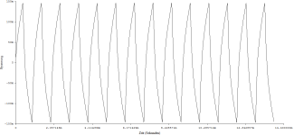 1kHz totale Übersteuerung = Rechteck 1Vp.png28.2 KB · Views: 31
 -
 2kHz totale Übersteuerung = Rechteck 1Vp.png22.3 KB · Views: 27
 -
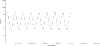 4kHz totale Übersteuerung = Rechteck 1Vp.png14.1 KB · Views: 28
 -
 8kHz totale Übersteuerung = Rechteck 1Vp.png11.9 KB · Views: 27
 -
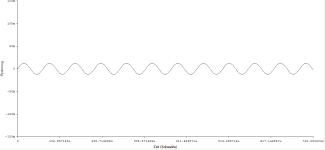 16kHz totale Übersteuerung = Rechteck 1Vp.png9.9 KB · Views: 32
Why on on earth do postings have to be this unfriendly.You aren’t making much sense. Any. If you don’t know please stay silent.
What´s wrong with a nice and friendly explanation.
Hans

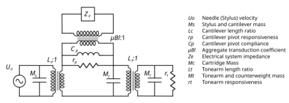
Only now does it get exciting, namely not when we look at active filtering (i.e. nfb allInOne solution), which would have no problems with processing and would come very close to the ideal, but when we look at the Aikidos, Salas, Pass Pearls ... of this world.
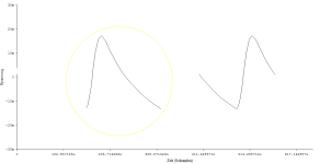
Assuming our fantastic 2V bump hits the first linear single-ended class-A jFet stage and is to be amplified with +30dB, the first one pops out over all the rails.
But, our pick-up is also a great low-pass filter (correctly terminated), second order with fh=15kHz, so it will attenuate the surge and deform it properly ... We could check whether this is the case with our simulators, completely without thinking.
always friendlyWhy on on earth do postings have to be this unfriendly.
What´s wrong with a nice and friendly explanation.
"Khz" is wrong
kHz is right
please do it in the right way Hans
 .
.thx
HBt.
Here are my measurements. (Note I use a 3-stage tube phono preamplifier with passive EQ between the stages, so overloading is not an issue).
https://www.diyaudio.com/community/threads/measured-phono-signal-levels.372498/
https://www.diyaudio.com/community/threads/measured-phono-signal-levels.372498/
👍(...) I think stylus geometry and cantilever material/construction will have a bigger impact on how clicks and pops are handled rather than all-active vs passive provided neither preamp is driven anywhere near overload.
right.
This is relevant here from the above cited post of mine:
... it seems the highest modulation velocity is around 30...35 cm/s @1kHz, which is 17dB above 5 cm/s. Then +20 dB is a safe margin. In my case it means 5 mV might come from the cartridge at extreme conditions, and 28Vrms might appear at the phono output. That is 80V peak-to-peak signal level!
(As I mentioned my phono gain is on the high side with 50dB; if we calculate with a more common 40dB, the output swing would be 26Vpp. A phono preamplifier made of opamps with +/-15V PSU can just handle it)
I have marked all posts with a "like".Here are my measurements. (Note I use a 3-stage tube phono preamplifier with passive EQ between the stages, so overloading is not an issue).
https://www.diyaudio.com/community/threads/measured-phono-signal-levels.372498/
I am particularly pleased about the analogy in the "Bewegungsbild".
Attachments
Cool,That is 80V peak-to-peak signal level!
I keep saying it, phono equalization can only work properly with tubes and anode voltages much higher than 200Vdc.
All the junk of my childhood didn't work at all - oh, if only I had ...
😱
DUAL - everything was junk back then, it was already transistorized - BJTs
28.3Vrms
is ( a little bit) nonsense ...
Before I get beaten, I would like to point out that I like tubes too, I just don't use them anymore.
HBt.
+/- 15Vdc supply rails solve any subjective problem
then all's well - the porridge has been eaten!
Bye,
HBt.
Ok,(...) (As I mentioned my phono gain is on the high side with 50dB; if we calculate with a more common 40dB, the output swing would be 26Vpp. A phono preamplifier made of opamps with +/-15V PSU can just handle it)
then all's well - the porridge has been eaten!
Bye,
HBt.
My observation is that clicks and pops are hardly noticable on a tube RIAA preamplifier, that has passive (interstage) frequency correction, no feedback. On the other hand, clicks and pops can be very disturbing on an operational amplifier based RIAA preamplifier that uses correction in the feedback. Both are flat to +/- 0.1 dB, the opamp based pre has >20 dB overload margin, and still... Subjectively they are completely different, the tube unit suppresses clicks, the opamp unit emphasizes them. It is hard to find the reason by measuring them, but immediately evident by listening to them. I don't mention models or schematics, it seems related to the active devices.
Spot on! 👍
"related to the active devices" - and the fact that one has passive RIAA ... whilst the other has active.
And the wheel keeps turning
Let us simply believe the statements and logically search for a correct answer to these observations:
It can't be that difficult!
HBt.
On the other hand, clicks and pops can be very disturbing on an operational amplifier based RIAA preamplifier that uses correction in the feedback. Both are flat to +/- 0.1 dB, the opamp based pre has >20 dB overload margin, and still... Subjectively they are completely different, the tube unit suppresses clicks, the opamp unit emphasizes them. It is hard to find the reason by measuring them, but immediately evident by listening to them. I don't mention models or schematics, it seems related to the active devices.
Spot on!
"related to the active devices" - and the fact that one has passive RIAA ... whilst the other has active.
Let us simply believe the statements and logically search for a correct answer to these observations:
It can't be that difficult!
HBt.
(As I mentioned my phono gain is on the high side with 50dB; if we calculate with a more common 40dB, the output swing would be 26Vpp.
A 50dB phono stage is high for MM (and will suit HOMCs) - but is not "high" for an MC phono stage.
I thought this was an Oscar Wilde, but turns out it's called Sayre's Law "In any dispute the intensity of feeling is inversely proportional to the value of the issues at stake."
All good fortune,
Chris
All good fortune,
Chris
The second issue is that topology could possibly have a positive impact on a lower reproduction level from pops and clicks, which cannot be anything other than based on personal experience.
Until now Icsaszar, Dave Crawley, myself and maybe Drbulj are assuming that passive filtering has a positive effect in reducing pops and clicks.
Coming with proposals to measure things is totally useless, incomparable and unreproducible, in short a waste of time.
I think the entertainment value is quite decent for some of the protagonists.
#
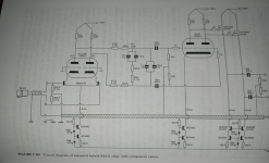
So let's stick with the following topology:
Gain block 1
loaded by the passive first order filter with two poles and a zero
followed by Gain block 2.
Many experts prefer this Lego brick composition. There is no question that this scenario can work perfectly - and in the majority of cases it does.
The only question that remains now is how to implement the two amplifier components. Perhaps also how to implement the equalizing low-pass filter.
In this context, one can make a multitude of mistakes.
I am happy to have a few concrete pieces of butter with the fish.
kindly,
HBt.

Hi,Gentlemen, surely we can move this discussion to fruitful topics which will help us design better RIAA preamps?
Have we got a 'repeatable' test that allows us to measure the effect of CpP (clicks or pop)? Can we simulate a CoP in LTspice with a simple impulse (we can add the effect of cartridges, loadings bla bla to taste)?
I'm a fan of simple feedback OPA designs like Bonsai but the last time I designed such a beast for a commercial product was the last Millenium.
But I'm really interested in how exotic beasts with passive EQ and zillion volt supplies perform compared to my simple farm animals.
Will the designers of da exotic beasts show us the end result of passing an impulse through their pets and compare the final result with simpler designs ... at least in SPICE world.
Which of the exotic beast should we use for this comparison?
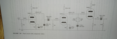
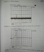
I simulated a single op amp with Riaa correction in the feedback versus a three stage design, each stage having a gain of 20dB with a 75usec passive filter after the first stage and a 3180usec/318usec passive filter after the second stage.
Both versions had the same 40dB@1kHz gain and about the same noise, all amps based on the OPA1656.
Stimulating was done with a 70mV 100usec wide triangle peak such as Bob Cordell has recorded in #8.
As almost to be expected, outcoming signal from both was identical. 🤣
Hans
Let's saddle up:
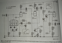
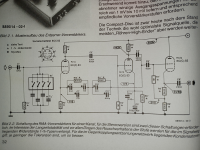
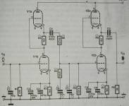
A few quick snapshots from my shelf, Morgan Jones, R. zur Linde and J. P. Güls may forgive me.
A few quick snapshots from my shelf, Morgan Jones, R. zur Linde and J. P. Güls may forgive me.
Attachments
- Home
- Source & Line
- Analogue Source
- RIAA Overload Performance’ to Encoded Signals (i.e. the Music) and Response to Clicks and Pops (Unencoded)