As mentioned earlier, this tread addresses overload by encoded music and non Riaa encoded pops and clicks.
The overload aspect was already declared to be a non issue, but for some reason the questions still keeps popping up one after the other some of them almost in an aggressive way, I will skip them from now on.
The second issue is that topology could possibly have a positive impact on a lower reproduction level from pops and clicks, which cannot be anything other than based on personal experience.
Until now Icsaszar, Dave Crawley, myself and maybe Drbulj are assuming that passive filtering has a positive effect in reducing pops and clicks.
Coming with proposals to measure things is totally useless, incomparable and unreproducible, in short a waste of time.
But the more people support this thesis, the higher the likebility.
Nothing more, nothing less.
That's were DiyAudio can help people to come to a final decision in this jungle of possible designs.
I also mentioned that @Hierfi came with an interesting AD844 design without feedback with the passive Riaa network in the current output.
This looks to me as another promising design.
When looking for the simplest solution, there is probably no way around the Riaa network in the NFB loop.
Hans
I measured Aikido Phono 1+ discrete JFET preamplifier with 48V single supply voltage. It is a 2 stage design with passive equalization.
https://www.audiosciencereview.com/forum/index.php?threads/aikido-phono-1-mm-preamp-review.60791/
It has considerably worse HF overload margin than my FB EQ Openamp. It also has much higher distortion. There are tons of myths in diyaudio.
https://www.audiosciencereview.com/forum/index.php?threads/aikido-phono-1-mm-preamp-review.60791/
It has considerably worse HF overload margin than my FB EQ Openamp. It also has much higher distortion. There are tons of myths in diyaudio.

One of the myths seems a "gross" preference for feedback RIAA designs that seemingly excludes recognition of the overload capabilities of passive current RIAA networks. Truth as an affront to myths doesn't seem aided by the addition of superlatives to just of "prefer".I have no problem with disturbances from clicks and grossly prefer the feedback RIAA design.
I'm personally big friend of passive RIAA eq, that's because I used both and passive is better for my taste.
One thing what could explain is noise behavior of amp vs gain.
Higher the gain, better snr is obtainable, think this is understood, if not see datasheet of ssm2017 hbtaudio posted for whatever reason.
Passive RIAA will have huge gain (low noise) that is then attenuated by 40 db in HF region, as well as noise together with it, also pops and clicks.
Active (feedback) riaa will reduce amps gain at HF, by default reducing SNR and missing benefit of further attenuation by passive RIAA ....
Makes sense?
It's the 4 glasses of red wine you drink before dropping the needle into the groove that makes it sound better.Whole vinyl is mystery, measures worst (much worst) than mp3 when stylus touches the groove, and still makes you feel U are in best seat of opera house... I don't know why... It's subjective of course
😉
Not to me. How can lower gain make SNR worse? And how is lower gain less beneficial than attenuation?Active (feedback) riaa will reduce amps gain at HF, by default reducing SNR and missing benefit of further attenuation by passive RIAA ....
Makes sense?
All active feedback does not reduce the SNR because the gain reduces at HF. With all-active you get the best of all worlds: best SNR (note there are a few special cases where this might not be the case, and the disadvantage is in the region of 0.1-0.2 dB - but the active/passive design still does not match the all-active in overload), and always best overload performance. I do not believe passive handles clicks and pops differently to the extent it is measurably better. A click or pop is a signal and no different to any other electrical signal.
I think stylus geometry and cantilever material/construction will have a bigger impact on how clicks and pops are handled rather than all-active vs passive provided neither preamp is driven anywhere near overload.
I think stylus geometry and cantilever material/construction will have a bigger impact on how clicks and pops are handled rather than all-active vs passive provided neither preamp is driven anywhere near overload.
Last edited:
I can see
🤣🤣
Somehow I'm not thinking about listening music when reading thisIt's the 4 glasses of red wine you drink before dropping the needle into the groove that makes it sound better.
😉
🤣🤣
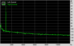
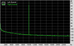
To debunk some so called myths, here the distortion spectra recorded at resp 1Khz and 10Khz both at 1Vrms out.I measured Aikido Phono 1+ discrete JFET preamplifier with 48V single supply voltage. It is a 2 stage design with passive equalization.
https://www.audiosciencereview.com/forum/index.php?threads/aikido-phono-1-mm-preamp-review.60791/
It has considerably worse HF overload margin than my FB EQ Openamp. It also has much higher distortion. There are tons of myths in diyaudio.
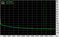
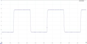
Third image shows the 19+20Khz IMD response.
Fourth image shows a +/- 0.6V square wave with the preamp fed from an anti Riaa signal.
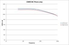
Fifth image shows the CMRR.
Fully differential Preamp has passive equalization.
These figures are as good as figures can be.
Hans
Attachments
This one ;absolute agree, two electromechanical parts of sound reproduction system, cart and speaker (together with room) far, few classes, bigger impact on result than any electronics involved in the middle.I think stylus geometry and cantilever material/construction will have a bigger impact on how clicks and pops are handled rather than all-active vs passive provided neither preamp is driven anywhere near overload.
Yes it is just a signal.A click or pop is a signal and no different to any other electrical signal
I did not anylize them, but by character these will be loaded with HF harmonics. Guess most annoying part of click and pop is in HF range... Might be I'm wrong.
Gentlemen, surely we can move this discussion to fruitful topics which will help us design better RIAA preamps?
Have we got a 'repeatable' test that allows us to measure the effect of CpP (clicks or pop)? Can we simulate a CoP in LTspice with a simple impulse (we can add the effect of cartridges, loadings bla bla to taste)?
I'm a fan of simple feedback OPA designs like Bonsai but the last time I designed such a beast for a commercial product was the last Millenium.
But I'm really interested in how exotic beasts with passive EQ and zillion volt supplies perform compared to my simple farm animals.
Will the designers of da exotic beasts show us the end result of passing an impulse through their pets and compare the final result with simpler designs ... at least in SPICE world.
Which of the exotic beast should we use for this comparison?
This is the same click in higher time resolution:
View attachment 1426062
and I agree that for a competent phono preamp design it should be no problem. Integrating character of the RIAA EQ response helps a lot and the click should have been much broader to send the preamp to output saturation or internal saturation.
Frequency representation does not help much (IMO) to evaluate the click or mistracking effect.
And yet, I have observed that some phono stages seem to emphasise "clicks & pops" more than others. IOW ... when you listen to these phono stages, you are more disturbed by clicks & pops than when listening to other phono stages?
Possibly they have a lower headroom - IOW, their +DC rail ... or the sum of the -ve & +ve DC rails is too low?
Yes to all.Have we got a 'repeatable' test that allows us to measure the effect of CpP (clicks or pop)? Can we simulate a CoP in LTspice with a simple impulse (we can add the effect of cartridges, loadings bla bla to taste)?
By increasing Rg for reducing gain?Not to me. How can lower gain make SNR worse? And how is lower gain less beneficial than attenuation?
But you are right, I don't know why is passive better really. I leave discussion to more experienced folk and read 😊
We can shorten the matter enormously and file it away immediately, while only looking at the core.
The core is a so-called lag filter, we have two time constants, a pole and a zero.
H(s) = (1+ s/omega2) / ( 1 + s/omega1)
This is followed by a second first-order low-pass filter with
H(s) = 1 / ( 1 + s/omega0) ...
Whether the combination of both transfer functions (this is a so-called descriptor, one!) is now executed passively or as an active filter is insignificant, namely first of all completely identical.
Let's return to the somewhat more difficult to understand area, the tools. Logarithmization, for example, is one of the better-known transformation tools.
H(jOmega) = F[h(t)]
or also
H(s) = L[h(t)]
We use Fourier and / or Laplace.
What is this h(t)? Well, this is the answer of our primitive and completely trivial low-pass filter with two poles and one zero, in somewhat simplified terms a simple 1st order filter, to a very short voltage jump on the input side.
Let's think of this as infinitely short and infinitely high ...
then the ensemble responds with h(t) = omega0 * e^(-omega0 * t). We should all remember this from school, from the better physics lessons in secondary school.
Basically, the case would have disappeared into thin air if it weren't for g(t), i.e. not the discharge function, but the charging function of a capacitor (its ability to store energy in an electric field is called capacitance), the so-called step response.
#
Yes, we can measure all relevant points. And yes, we can also calculate and even simulate everything.
Dear reader,
Please do not allow yourself to be constantly led astray by the deliberate heckling and disruption of a particular ...
thx
HBt.audio
PS
That was the short answer, with far too many words and I am infinitely tired.
By increasing Rg for reducing gain?
You aren’t making much sense. Any. If you don’t know please stay silent.
This is the entire three-stage combination, the typical MM pickup system (nominally) as a simple 2nd order low-pass filter with Q < 1 and posting #118.
We see the two components magnitude and angle, expressed as amplitude response and phase response, normalized we would talk about a so-called Bode diagram. Now we just have to excite this entire H(jOmega) with jumps and or pulses.
This can even be solved graphically, i.e. by drawing. Really by hand, a spectral synthesis or analysis also works by hand - my species had to practice this in college (when the dinosaurs were still alive).
Attachments

- Home
- Source & Line
- Analogue Source
- RIAA Overload Performance’ to Encoded Signals (i.e. the Music) and Response to Clicks and Pops (Unencoded)