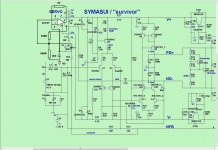
How does this adjustment compare to 26mVre?...............NS OPS -> 65-70mA per pair = ................
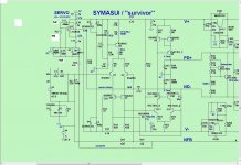
Here is what exactly matches my board in servo area.
Attachments
Last edited:
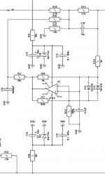
Try changing R28 to 220k for that 10:1 ratio and refit the servo opamp. See how it starts and how it behaves.
If there is almost no offset to correct, then the correction signal at the opamp output pin should be near zero volts ref Signal Return/ground.
If there is almost no offset to correct, then the correction signal at the opamp output pin should be near zero volts ref Signal Return/ground.
How does this adjustment compare to 26mVre?
It's equal to around 15mVre (70mA * 0R22) - this non-switching configuration has the lower optimal bias value than normal (according to distortion measurements on the prototype).
Assuming, the bias clamping mechanism is tuned the right way.
Thanks, useful comparison.It's equal to around 15mVre (70mA * 0R22) - this non-switching configuration has the lower optimal bias value than normal (according to distortion measurements on the prototype).
Assuming, the bias clamping mechanism is tuned the right way.
You mean R17=R22?I normally use a slightly different topology for non-inverting servo, utilizing a single capacitor.
Important thing - resistor pairs must be equal:
R18 = R24;
R12 = R22.
Idle current
Hi,
I have a simple question about (your) output stages.
For the future I'am planning a 3 way activ speaker system.
And I want to estimate the idle current.
What is the idle current of a complimentarily pair bipolar transistors (e.g. NJW0281g/NJW0302g in the NS-OPS or slewmaster)
or mosfet complimentarily pair (e.g. IRFP240/IRFP9249 in VHEX+ in the slewmaster)?
Is there a difference if the current is adjusted optimal?
Please Valery can you check this?🙂Oops... yes! Typo 😛
Attachments
Last edited:
Hi,
I have a simple question about (your) output stages.
For the future I'am planning a 3 way activ speaker system.
And I want to estimate the idle current.
What is the idle current of a complimentarily pair bipolar transistors (e.g. NJW0281g/NJW0302g in the NS-OPS or slewmaster)
or mosfet complimentarily pair (e.g. IRFP240/IRFP9249 in VHEX+ in the slewmaster)?
Is there a difference if the current is adjusted optimal?
Hi Ampi,
Idle current depends not only on the output device type (BJT, MOSFET, etc.), but also on the nuances of particular topology.
I thought I gave you the answer in Post #1600. Did I? 🙂
Cheers,
Valery
Please Valery can you check this?🙂
Looking good. It would be an interesting experiment 🙂
Just a note; on my Symasui, the servo works just fine. The issue is that there is about 2v offset at turn on. Within about 4 or 5 seconds the servo corrects it and it drops to zero offset. I assume that Thimios is working on bringing the initial offset closer to zero so the servo doesn't have so much to correct. Is this right?
Just a note; on my Symasui, the servo works just fine. The issue is that there is about 2v offset at turn on. Within about 4 or 5 seconds the servo corrects it and it drops to zero offset. I assume that Thimios is working on bringing the initial offset closer to zero so the servo doesn't have so much to correct. Is this right?
Hi Terry,
In general - yes, however we observed certainly strange servo behavior, which is not related to any design issues - Pete's integrator is just fine. Thimios is trying to localize the root of the issue - in his case, servo's involvement leads to the offset increase, comparing to no-servo version...
Mine actually behaved the same as Thimios' board did. I built four of them and all had slow settling of the offset at start up. It was tripping my DC detection. I'll have to dig them out and check into them some more.
It sounds like integrator itself starts with some noticeable offset, making the whole amplifier following its settling curve. As Thimios reported, the amplifier wth no servo behaves much easier, settling at 2.5mV offset practically right from the start.
Kind of odd.
Kind of odd.
With the changes Thimios made to correct the offset without the servo, does the initial offset change if the servo is reinstalled?
I don't think he made any changes to correct the offset. He just pulled the servo and powered it up from what I understood.
- Home
- Amplifiers
- Solid State
- Revisiting some "old" ideas from 1970's - IPS, OPS