It looks like a great amplifier as is. No real need for the servo.
Yes, it is great without servo and can use cheap transistor (example MJE340/350) for VAS with right compensation will be good enough. I made two amplifiers with this topology. First, I simplified Symasym with easily to find transistor here. According who built it, the high was better because slew rate is higher, but low slightly worse. Second, almost same as Symasui but no input cascode and 2EF output using 63VDC and cheap transistors. All worked without servo.
160mV&147 mV was measured against power gnd.-160mVdc at the input node cannot be right.
It should be a +ve voltage, because the base current comes from the +ve supply through R2 to Signal Ground and thence through R3 to Power Ground.
Check the voltage @ R3, looks like it is ~+3mVdc reference the Power Ground and 0.0mVdc reference the Signal Ground.
3mV indicates 300uA flowing from Signal Ground to Power Ground. This could be adjusted to be quite a bit less, but I don't know how it varies with temperature. Worth checking when cold, warm, hot.
Same error for the -147mVdc voltage.
Last edited:
I guessed you measured with reference to power ground. that's why we see -160mV and 154mV. These tell us that Signal Ground was not used as the reference.
Now back to whether it is +160mVdc or -160mVdc?
Now back to whether it is +160mVdc or -160mVdc?
Is it possible that the servo opamp was inserted back to front?
Or could it be latching up during start up and then taking a very long time to unlatch and restore correct offset.
Or could it be latching up during start up and then taking a very long time to unlatch and restore correct offset.
Ah now i am not at work desk, sorry i will answer tomorrow.I guessed you measured with reference to power ground. that's why we see -160mV and 154mV. These tell us that Signal Ground was not used as the reference.
Now back to whether it is +160mVdc or -160mVdc?
Is it possible that the servo opamp was inserted back to front
No,in this case we will have a shorted +/- 12v power supply not a functionall IPS.
Last edited:
Tested again.there isn't any error, it is -154mV AND -160mV.I guessed you measured with reference to power ground. that's why we see -160mV and 154mV. These tell us that Signal Ground was not used as the reference.
Now back to whether it is +160mVdc or -160mVdc?
Using signal gnd as reference point it is -141mV AND -145mV.
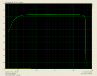
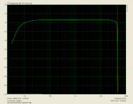
Testing Frequency Response and THD+Noice vs frec.
Attachments

Last edited:
To help avoid confusion, I'll start this analysis at the Signal Return/ground.
Follow the current route from Signal Return through R2 (22k) to Q1 base (+IN) up through the BE junction to R9 (47r) on through R8 (1k) Up through Q5 CE junctions through R5 (60r) through R4 270r to the +ve supply rail.
Conventional current is the reverse of that route. Conventional current flows down through R2 and develops a voltage where Vr2 = Ir2*22k
We expect the voltage at the top of R2 to be positive with respect to the bottom of R2.
That makes the voltage of R1 R2 junction, +ve with reference to Signal Ground. 145mV across 22k tells us that the current Ir2 is ~6.6µA, that current can only come from the base of Q1, since the other exit routes are blocked with capacitors.
You can do a similar analysis for the current route from +ve supply rail down to +IN and thence to Speaker Return/Power Ground.
Last edited:
Tested again.there isn't any error, it is -154mV AND -160mV.
Using signal gnd as reference point it is -141mV AND -145mV.
Testing Frequency Response and THD+Noice vs frec.
I must apologize for this tragic stupid mistake.
I had check testing cables 3 times and 3 times was mistake.(red cable to common on multimeter,these testing cables are gray and only at the end are colored,Fluke stupid selection)
No, theory is theory and can't be upside down.

These measurements are positive +145,+141
Sorry again.
Last edited:
here is the testing cables
Attachments


Last edited:
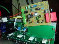
Frankenstein continue
Wolverine IPS+NS OPS
Wolverine IPS+NS OPS
Attachments
-
 IMD swept tones.PNG24 KB · Views: 136
 -
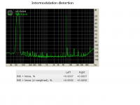 Intermodulation distortion.PNG26.6 KB · Views: 147
 -
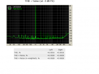 THD+Noise.PNG25.7 KB · Views: 146
 -
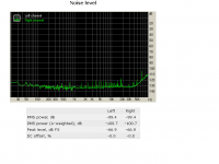 NOISE LEVEL.PNG22.9 KB · Views: 142
 -
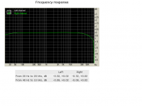 FREQUENCY RESPONSE.PNG20.8 KB · Views: 267
 -
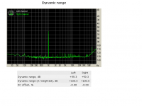 Dynamic Range.PNG20.8 KB · Views: 274
 -
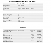 DETAILS.PNG22.9 KB · Views: 288
 -
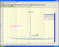 25mv bias 1.5w.PNG114.4 KB · Views: 140
 -
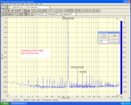 25mv bias 57w.PNG116.3 KB · Views: 150
 -
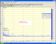 57W.PNG88.5 KB · Views: 147
OK, I looked closer at all the recently published schematics of Symasui (example - post 1576) - servo's topology is wrong. I'm sure it's a "typo" kind of mistake, but it's there.
The way the servo's output is connected (to inverting input of the amp), servo has to be non-inverting - as we remember, servo provides the negative feedback. The way it's arranged right now - it's inverting (even in this case it's strange). So, it's increasing the offset, instead of zeroing it out (as we could see).
The way the servo's output is connected (to inverting input of the amp), servo has to be non-inverting - as we remember, servo provides the negative feedback. The way it's arranged right now - it's inverting (even in this case it's strange). So, it's increasing the offset, instead of zeroing it out (as we could see).
OK, I looked closer at all the recently published schematics of Symasui (example - post 1576) - servo's topology is wrong. I'm sure it's a "typo" kind of mistake, but it's there.
The way the servo's output is connected (to inverting input of the amp), servo has to be non-inverting - as we remember, servo provides the negative feedback. The way it's arranged right now - it's inverting (even in this case it's strange). So, it's increasing the offset, instead of zeroing it out (as we could see).
Could this be why I came up with an analysis and conclusion that the DC servo was +ve feedback?
idle current
Hi,
I have a fundamental question about (your) output stages.
For the future I'am planning a 3 way activ speaker system and I want to estimate the idle current.
What is the idle current of a complimentarily pair bipolar transistors (e.g. NJW0281g/NJW0302g in the NS-OPS or slewmaster)
or a mosfet complimentarily pair (e.g. IRFP240/IRFP9249 in VHEX+ in the slewmaster)?
Is there a difference if the current is adjusted optimal?
OK, I looked closer at all the recently published schematics of Symasui (example - post 1576) - servo's topology is wrong. I'm sure it's a "typo" kind of mistake, but it's there.
The way the servo's output is connected (to inverting input of the amp), servo has to be non-inverting - as we remember, servo provides the negative feedback. The way it's arranged right now - it's inverting (even in this case it's strange). So, it's increasing the offset, instead of zeroing it out (as we could see).
Hi Valery,
Is there a simple fix for this?
Actually, I'm wrong. The topology is fine. Pictures are relatively low resolution.
However, it could influence your analysis, Andrew, as well, I believe.
Well, the only thing, able to lead to the error in servo's operation, I can think of - parasitic conductance through some bad parts...
However, it could influence your analysis, Andrew, as well, I believe.
Well, the only thing, able to lead to the error in servo's operation, I can think of - parasitic conductance through some bad parts...
Optimal does not apply to a mosFEToutput stage. It just gets better the higher the bias current. Borbely tells us to go for >=500mA total bias irrespective of how many paralleled pairs one installs.Hi,
I have a fundamental question about (your) output stages.
For the future I'am planning a 3 way activ speaker system and I want to estimate the idle current.
What is the idle current of a complimentarily pair bipolar transistors (e.g. NJW0281g/NJW0302g in the NS-OPS or slewmaster)
or a mosfet complimentarily pair (e.g. IRFP240/IRFP9249 in VHEX+ in the slewmaster)?
Is there a difference if the current is adjusted optimal?
Optimal ClassAB does apply to a standard EF output stage and requires approximately 20 to 26mV across the output resistances. Some of this resistance is inside the BJT. Because of this internal resistance the correct method is to examine the distortion residual and adjust to minimise the crossover portion of that residual. D.Self shows pics of under, optimal, over biased.
Last edited:
Hi,
I have a fundamental question about (your) output stages.
For the future I'am planning a 3 way activ speaker system and I want to estimate the idle current.
What is the idle current of a complimentarily pair bipolar transistors (e.g. NJW0281g/NJW0302g in the NS-OPS or slewmaster)
or a mosfet complimentarily pair (e.g. IRFP240/IRFP9249 in VHEX+ in the slewmaster)?
Is there a difference if the current is adjusted optimal?
Hi Ampi,
NS OPS -> 65-70mA per pair = 195-210mA for 3 pairs in total;
VHex+ -> 80-90mA per pair = 160-180mA for 2 pairs in total.
Note that these output stages are very different in many aspects.
Cheers,
Valery
- Home
- Amplifiers
- Solid State
- Revisiting some "old" ideas from 1970's - IPS, OPS