Does that mean the output waveform is at least divided by 2, suggesting the minimum pulse width is at minimum equal to the period of the 24MHz, or about 42nSec, as the fastest switching time between a rising and a falling edge. Does the FIRDAC always have the same number of rising and falling edges per sample?EDIT: These dacs are usually clocked at 22/24MHz or else 11/12MHz in order to be able to play DSD256. However it not the fundamental clock frequency that tends to cause problems so much as it is the fast risetime. Sometimes slowing the risetime a little can find a sweet spot where EMI/RFI is less, but the dac is still operating well as intended.
The reason for asking is that it shouldn't matter the nature of the rising or falling waveforms, rather they can be significantly different. That in the summation of capturing complete rising and falling waveforms of equal numbers can only generate a constant DC offset. In other words there is no signal in complete rising or falling waveforms having identical repetitive shapes and transition numbers. However if these become variantly truncated by increased clocking frequency causing overlap, or by feedback networks that can't respond to the completion of those transient waveforms this suggests variant DC shifting creating IM artifacts.
Just to show that the relatively large differences between the two third-order product are purely caused by the Shift Register Firdac circuit, here are:It's strange that the two third-order intermodulation products have such a large difference, almost 10 dB, despite their small frequency ratio. They are -102.93 dB and -112.77 dB with respect to the desired tones. (As an RF designer, I always refer the intermodulation products to the level of one of the tones, apparently different from the ARTA convention.)
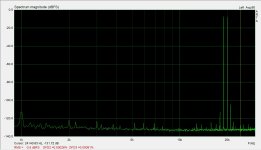
Image 1) The IMD from the current Shift Register Firdac, both 19&20Khz signals at -6dB.
The two 3rd order products are quite different.
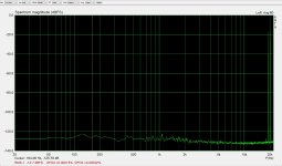
Image 2) IMD from your Solid State DAC, taken with both 19&20Khz at -16dB.
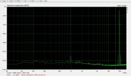
Image 3) IMD from the Solid State DAC with both 19&20Khz at -6dB.
A huge difference between 2) and 3) but the third order products have equal amplitude in both cases.
So maybe the current shift register Firdac should also be given a try at -10dB because the drop in IMD is significant.
Hans
Attachments
Just to clarify a few points where I may not have been sufficiently clear...The biggest problem in audio design, both diy and professionally, IMHO has to do with the mindset of engineers. I understand the mindset pretty well having been a professional engineer most of my life. Its just that as engineers we can get stuck focusing on what we know how to measure.
@soundbloke said something I through was pretty profound in another thread. It was this:
I would suggest the most important misconception is the assumption of linearity in our hearing. Our learning capabilities are (predominantly) irreversible and therefore very non-linear. Unless rigourous blind testing is carried out on a per listener arrangement (which will often be practically extremely difficult), there is little reliable information to separate the well-trained listener from a delusional one when we approach commonly accepted hearing thresholds. Regardless of our physiology, we all have a capability to train our hearing on minute details that an untrained listener would find inaudible. Likewise we all possess a substantiative capability to delude ourselves into hearing soemthing we are not. Perception and sensation are not the same thing...
https://www.diyaudio.com/community/threads/measuring-the-imaginary.409662/post-7613254
Its pretty much the same same thing about learning to hear that Howie Hoyt talked about after having submitted to years of ABX testing (it may even be that Amir has learned to listen more skillfully after going through the Harmon training). Its that people can learn how to hear little things which are inaudible other people, but the skill has to be learned methodically over time. However, there is a big problem with all this which is that people can also be quite deluded about what they are hearing. Too many EE's only believe in the "humans are quite deluded when it comes to hearing" part. They deny that anyone can be well-trained to hear what would be inaudible to others. That view is quite at odds with what soundbloke said.
Okay, so far? If so, I will try to tie it back into its relevance to this thread.
Learning occurs all the time in all that we do - at least all of the things that we are aware that we do. Purposeful learning (training) is just where we have some emotional driver to direct the process and highlight the relevant details. A skilled listener may not then need purposeful training, just the relevant experience.
When something is learned, it is generally not unlearned: It is a very non-linear process and makes our full hearing capabilities very difficult to model.
In forming our perception, there exists a substantial capacity for delusion - such as hearing a detail that is not actually sensed.
It is often stated that blind testing can identify delusions in listening evaluations, and I suspect for the most part this is actually true.
However, our inherent non-linearity also means that our hearing capability now can be highly dependent on various emotional drivers and what we might have learned previously: Thus self-proclaimed "golden ears" are afforded a valid defense too.
Hence perception and sensation are not the same thing, and the task of the audio engineer is restricted to optimizing the fidelity of the sensation.

I have the following to comment on the figures.
In Arta's manual I can find:
second order IMD in percent is: 100* I(f2-f1)/I(f1+f2)
third order IMD in percent is: 100* I(2f1-f2)+ I(2f2-f1)/I(f1+f2)
In my IMD measurement:
I(f2-f1) = -119.27dB or 1.08768e-6
I(2f2-f1) = -109.43dB or 3.37676e-6
I(2f1-f2) = -119.27dB 0r 1.08768e-6
Rms level according to Arta was -3.5dBrms, so both f1 and f2 are at -6.5dB.
I(f1+f2) = Power(10;-3.5/20) = 0,668344
Applying the above figures gives:
IMD second order at 0,00016% or -115,8dB (Arta mentions 0,00026% ??)
IMD third order at 0,00067% or at -103,5dB (Arta mentions 0,00091% ??)
Now doing the same calculculation for Bohrok's spectrum:
I(f2-f1)=-140dB or 1.0e-7
I(2f2-f1)= -114dB or 1.99526e-6
I(2f1-f2) = -116dB or 1.58489e-6
Peak level to graph -1.97dB and Rms level at -4,97dB, so both f1 and f2 are at (-1,97-6.02) = -7.99dB.
I(f1+f2) = Power(10,-4,97/20) = 0.564287
Again applying these figures the same way as above:
IMD second order at 0,000018% or -135.0dB
IMD third order at 0,00063% or -103.9dB
I may have done something that may cause the difference between Arta's and mine calculation, roughly a sqrt(2) but by using the same calculation, Bohrok's figures and mine are 1:1 comparable.
What can be seen is that both our third order IMD with resp. -103.5 and -103.9 are within 0.4dB !!
However Bohrok's second order IMD is 19.2dB below mine with -135,0dB versus -115.8dB.
This could well be caused by my Lynx A/D converter having a specified dynamic range of 117dB.
Hans
After all Arta was fully correct and reproduceable because I made a silly error in the scale factor of my graph, but not in Bohroks calculation.
Now I get the same figures as Arta calculated, IMD2 = 0.00026% or -111.7 dB and IMD3 = 0.00091%. or -100.8dB.
This means that Bohrok measures 23.3 dB less IMD2 and 3.1 dB less IMD3.
His A/D converter must be far superior to my Lynx.
Hans
Why does it need to be the ADC? He uses OPA1678 rather than NE5532, he cut off the third stage and he has a different printed circuit board.
Just to show that the relatively large differences between the two third-order product are purely caused by the Shift Register Firdac circuit, here are:
Image 1) The IMD from the current Shift Register Firdac, both 19&20Khz signals at -6dB.
The two 3rd order products are quite different.
One would expect some difference between the IM3 products (with the highest-frequency product being the largest) because the loop gain of op-amps drops with frequency, and the filter components cause extra frequency-dependence of the loop gain (for example C16 and C27 in stage 2). No idea why the difference is so large, though; some weird compensation effect maybe?
Image 2) IMD from your Solid State DAC, taken with both 19&20Khz at -16dB.
Image 3) IMD from the Solid State DAC with both 19&20Khz at -6dB.
A huge difference between 2) and 3) but the third order products have equal amplitude in both cases.
Theoretically, a 10 dB signal reduction should reduce the third-order products by 30 dB and increase the distance to the tones by 20 dB. That applies as long as higher-order distortion doesn't cause substantial distortion products that fall on top of the third-order products.
True, but my Lynx could never display such a large dynamic range.
With only 117dB I don’t know whether the 1Khz product is from the Firdac or from the Lynx.
Hans
With only 117dB I don’t know whether the 1Khz product is from the Firdac or from the Lynx.
Hans
Corrected overview. I still notice that the distortion only goes from quite low to very low when something is changed in the second stage: either the biasing conditions or the op-amps.
Conclusion, we need measurements of audio band from @bohrok2610 at the I/U conversion output, the CM Servo output and the LPF Output PLUS a measurement of the spectrum supersonic (preferably out to 20MHz) of same.
I still have a gut feeling we ultimately see effects of the very large levels of switching noise inherent to RTZ DAC's.
My suggestion would still be to move the actual RF filtering of any CM and DM noise relating to the DAC switching ahead of the active circuit. Using CLC we can achieve a 3rg order lowpass before the I/U conversion, which itself could be laid out as MFB filter giving us a 5th order roll-off above the audio band.
Then focus the active circuit strictly on inherent common mode rejection and low (and flat with frequency) distortion in the audio band and for the noise from the noise shaping, meaning we need a fairly wide bandwidth.
I would probably suggest a composite device, with a low noise, low distortion OPA with decent bandwidth upfront and a high current output very high speed Op-Amp for the output stage (could be made differential).
So let's say something like OPA2210 or say OPA1611 (LT1115/1028?)) with a THS6012/TPA6120 as second stage with enough gain to compensate the loop gain lost by the net gain of the I/U conversion stage (view it as standard inverting amp with the effective output impedance of the DAC).
The emitter follower output of the CFB OPA will give low enough output Impedance at the actual I/U converter output to avoid any issues with noise feed trough.
Make the second stage so you get a non-Inverting and an inverting stage with identical output gain, making it a compound "Birt circuit" and a low noise precision FET input Op-Amp as DC servo for the circuit (feeding in the +input of the "inverter" and we get everything we want from a conceptual views.
An outwardly very simple single stage circuit with a simple feedback loop that is differential, is already protected from high levels of supersonic noise by a purely passive circuit and can be used with an LC filter (or line output transformer) on the output to directly drive SE and BAL outputs equally well.
Just my thoughts. Sorry for interrupting the petty bickering, as you where...
Thor
I'd say, build one and see how well it works.
I will do something like that.
However my design will avoid the large levels of switching noise from RTZ by using an alternative mitigation strategy against ISI that combines the benefits of NRZ and RTZ (and which I figured do to the time you kindly spent discussing the subject with me) and yes, it will use a passive filter before the active stages and a single stage, fully differential output, though fully discrete.
And we will indeed see soon.
I have used FDA circuits before with DAC's showing similar problems with common mode noise (though IC) and found that the FDA / Birt circuit is both objectively and subjectively preferred to the kind of circuit you showed.
Thor
That sounds like a very exciting project! I appreciate you sharing your approach and the thought process behind it. It's clear you've been putting a lot of consideration into this design.
It's particularly interesting to hear about your alternative mitigation strategy for ISI. Combining the benefits of NRZ and RTZ while avoiding the switching noise of RTZ sounds like a promising approach.
It's particularly interesting to hear about your alternative mitigation strategy for ISI. Combining the benefits of NRZ and RTZ while avoiding the switching noise of RTZ sounds like a promising approach.
By switching noise of RTZ is that random or correlated noise?
By inherent nature, RTZ DAC's switch a full cycle for every H.
This creates common mode "clock subharmonics or clock feedthrough (not harmonics, as we are always at frequencies at or below the clock for fundamentals), if we want to persnickety)" compared to a NRZ DAC.
Here an example of a NRZ DAC with 75% duty cycle (common in commercial DAC's, e.g. Burr Brown DSD1700:
The differential mode signal, as considered by the filter, can be seen to have one “+1” state, one “-1” state and one “neutral” position which is assumed for one quarter of the bit time. Unfortunately, the common mode signal is not zero. While it is true that it doesn’t contain any information, it is a rather hefty HF signal. This signal is supplied unattenuated to the first pair of op-amps which are required to attenuate it without exhibiting significant nonlinearities to affect the wanted signal. Only the best jfet op-amp will do here (the OPA627). Another high-quality op-amp (MAX427) was found to produce spectacular amounts of noise and distortion (0.1%).
Note here in the DSD1700 block diagram the "Duty Generator":
So we have a lot of common mode noise caused by the DAC switching at the update clock.
The noise is not correlated with the audio, but correlated with the clock and noise shaper.
With NRZ the level of this steady state noise at the FIR clock frequency is equal to full scale.
I still remember early DS DAC's that had major problems with this and basically worked poorly with Op-Amp most Op-Amp's common then in audio, needing to shift to current feedback designs at 150Mhz unity gain bandwidth to sound good (or more alternative solutions as covered in my "Valve analogue stages" article).
It's particularly interesting to hear about your alternative mitigation strategy for ISI. Combining the benefits of NRZ and RTZ while avoiding the switching noise of RTZ sounds like a promising approach.
Allow me to keep a few personal secrets. MvG is aware of my ideas and is of course free to comment.
I would instead suggest a mitigation strategy for MvG's DAC, that is kind of trivial to implement, at the cost of doubling up the DAC devices.
I cannot claim credit, it is in principle found here in Bruno Putzney's paper:
https://www.researchgate.net/public...s_for_high-performance_discrete_AD_converters
MvG's DAC has 50% duty Cycle. Let us say we add a second complete DAC section, operated with opposite polarity RTZ clock. So whenever the main DAC has a Zero following a One, the auxiliary DAC has a One following a Zero.
The resultant combined waveform substantially resembles an NRZ DAC, with much lower glitch energy from NRZ. Using illustrations from Bruno's article again:
The common-mode component is now clean, save for any spikes caused by unequal rise and fall times. These spikes are so short (<1ns) that supplementing the first filter capacitor with a pair of much smaller ground-referenced ones will rid the signal completely of common-mode.
I have used what amounts to a variant of this in all the higher end iFi DAC's using complete DAC's to operate according to this interleaving principle and having the same passive filter structure. At least commercially this was very successful with a strong reputation for sound quality.
I did make the suggestion to MvG in our discussions in private, but he was not very keen on the idea.
Another possible improvement to MvG's DAC that I think he may agree with is to move from equal bit weights to a different function, I will leave MvG to post his rather excellent note on the the subject which he graciously shared with me.
Personally I would suggest something based on Kaiser Window function. It does need at least 0.1% tolerance resistors.
In my view doing these two steps would materially improve on MvG's excellent and simple design and arguably make it more into something like a DSD1700 made in discrete logic. At which point we may wish to up the clock to 4 X fir clk and use 75% Duty Cycle instead of 50%.
Note, what I write is not intended as criticism. Merely my thinking based on dealing with the same underlying issues in IC based DAC's.
Thor
Last edited:
Perhaps Marcel would be willing to say something about his point of view?...he was not very keen on the idea.
Regarding upping the clock frequency, there would be some increased phase noise. Some unpublished experiments suggest that very low levels of close-in phase noise produce audible effects. IOW, its not only about reducing CM noise. There are always tradeoffs.
Last edited:
Great posts guys its proving really interesting reading .
I'm quite enjoying Marcels FIRDAC ,I'm still running it SE without last active stage but looking forward to trying out different things with it .
Its very different to my AYA2 which is still currently my favourite but I like it better than various Sabre dacs etc ive tried
I'm quite enjoying Marcels FIRDAC ,I'm still running it SE without last active stage but looking forward to trying out different things with it .
Its very different to my AYA2 which is still currently my favourite but I like it better than various Sabre dacs etc ive tried
Regarding AYA2, if Marcel's dac is run with clean, well isolated USB, and clean isolated dac power, that's the first step to getting it sounding better. Going from Amanero to I2SoveruUSB (with two isolated +5v power supplies) was a serious improvement here.
I've had AYA2 over 15 years and its had a lot done to it , the regs, I/V resistors etc have been changed , I'm on my last TDA1541A S2 so ideally would like a newer dac so I can retire the old workhorse . For such old tech its just sounded more real to my ears than other dacs , Marcels so far showed most promise
I'm still using separate shunt regs and PSU's for Marcels , I'm currently using a HDMI to I2S straight into the PCM2DSD , I'm also trying HQplayer to run the dac DSD , lots to try yet .
BTW I still need to try your other suggestions , I'm going to try closely matched 3k MELF resistors first
I'm still using separate shunt regs and PSU's for Marcels , I'm currently using a HDMI to I2S straight into the PCM2DSD , I'm also trying HQplayer to run the dac DSD , lots to try yet .
BTW I still need to try your other suggestions , I'm going to try closely matched 3k MELF resistors first
I also have AYA2 with Audial USB card. I never liked it so it has been gathering dust for more than 5 years. This just goes to show why I don't put any weight on subjective preferences.Its very different to my AYA2 which is still currently my favourite but I like it better than various Sabre dacs etc ive tried
- Home
- Source & Line
- Digital Line Level
- Return-to-zero shift register FIRDAC