3sec with mouse work is very bad idea if i make 200pcs tuning sets in my device per day. i want "one click" functionality)you would have to put the file in a target folder , the exe would have to always keep newest version on its command string....
Idk ..... very unusual automation.
how about just open the dsp program and simply drop it in yourself. It only takes about 3 sec out of your day. 🤖🔊🔉🔇🔈♥️
I think about autodetect file change interrupt script for me, like one way for example
3sec with mouse work is very bad idea if i make 200pcs tuning sets in my device per day. i want "one click" functionality)
I think about autodetect file change interrupt script for me, like one way for example
have you seen Raimonds Apl TDA software at work? It takes very quick measurements and can see time domain very fast as you make changes
maybe that is something you should steer your Interest's into. I just don’t see why you would want to make 200 fir a day without a new measurement in each iteration…
the TDA software does just that …does a measurement every second , and shows live results as you make changes
Last edited:
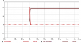
Is there a way to make a linear phase "all-pass" filter in RePhase with a 100% Step peak to prevent any high frequency loss or is such a digital filter even possible ? When I try to create one, the step is @ 94.2 % and haven't figured out how to improve upon that.
Thanks much.

Thanks much.
Is there a way to make a linear phase "all-pass" filter in RePhase with a 100% Step peak to prevent any high frequency loss or is such a digital filter even possible ? When I try to create one, the step is @ 94.2 % and haven't figured out how to improve upon that.
Thanks much.
View attachment 1008691
No clue , one of the actually smart ppl should step in
but isn’t that just a brick wall filter ?
I’m curious now too 🔈🔊🔉
I tried a BW filter in comparison and it had more issues than creating a LP filter with no frequency, phase or XO configurations.No clue , one of the actually smart ppl should step in
but isn’t that just a brick wall filter ?
I’m curious now too 🔈🔊🔉
That is a Dirac Pulse where the impulse changes from zero to 100 % over a single sample and back again. What you have there is as good as can be, the impulse is already at 100% to get the step response at about 94%. The higher the sample rate the shorter the sample period will be to extend the response out but will ultimately be band limited in reconstruction.Is there a way to make a linear phase "all-pass" filter in RePhase with a 100% Step peak to prevent any high frequency loss or is such a digital filter even possible ? When I try to create one, the step is @ 94.2 % and haven't figured out how to improve upon that.
Attachments
Ah ha ! Yes of course!That is a Dirac Pulse where the impulse changes from zero to 100 % over a single sample and back again. What you have there is as good as can be, the impulse is already at 100% to get the step response at about 94%. The higher the sample rate the shorter the sample period will be to extend the response out but will ultimately be band limited in reconstruction.
I can’t figure out why I can’t ever think of the answer …. It’s right there !!!
Thanks Fluid.That is a Dirac Pulse where the impulse changes from zero to 100 % over a single sample and back again. What you have there is as good as can be, the impulse is already at 100% to get the step response at about 94%. The higher the sample rate the shorter the sample period will be to extend the response out but will ultimately be band limited in reconstruction.
So to avoid the inherent HF loss I should substitute the "all-pass" filter for a delay the length of ((#taps/2)/sample rate) as a substitute "spacer" to maintain the relative parallel timings.
I learned something new today.
In rephase set the desired sample rate and output format add no filters of any kind and generate an impulse. That will make a Dirac Pulse.
That is how I made the plot above using exact-center-frequency, 176400 and 256K taps (and the 1st empty frequency bank set to "linear-phase".In rephase set the desired sample rate and output format add no filters of any kind and generate an impulse. That will make a Dirac Pulse.
The number of taps doesn't matter so much for this because there are only two sample values and the magnitude and phase is flat. The bank can be set to anything as long as no filter is set. rephase then generates an impulse with flat magnitude and phase, the Dirac Delta or Pulse. There is no high frequency loss, what you have is already as "perfect" as it can be. The step is different because it is the integral of the impulse. If maths helpsThat is how I made the plot above using exact-center-frequency, 176400 and 256K taps (and the 1st empty frequency bank set to "linear-phase".
https://www.quora.com/What-is-the-difference-between-the-step-response-and-the-impulse-response-in-system-theory#:~:text=where we clearly see that,integral of the impulse response.&text=The step response is the integral with respect to time,time of the step response.
I hadn't thought of that method. Great idea.Iterative REW / RePhase Workflow Method
I don't think I have seen this workflow referenced before, or if I did, I didn't recognize it as such.
FWIW, I stumbled on a REW feature that I was unaware of that can be used in conjunction with RePhase's multiple banks. Instead of measuring, creating a filter, applying the filter, remeasuring and reiterating, the multiple passes can be done in REW without physically remeasuring multiple times.
For example, if one does a single pass 5dB cuts filter off the top, REW will only generate up to 17 coarse PEQs for RePhase (not much detail).
If you try to generate 3 sets of filters from sub-frequency ranges to get more detail (e.g. low, medium, high), REW doesn't handle the aggregated boundary edge transitions very well.
As an alternative, one can make 5 - 1dB cuts filters, each based on its real or predicted predecessor and end up with 5 sets of 17 PEQs (vs 1 set of 17). Each set would get loaded into a respective RePhase bank and combined in a single filter using the minimum-phase setting to adjust both frequency amplitude and phase.
To do this, use REW's EQ function, setup your desired target curve and instead of doing the entire N dB "Match Response to target" cut, do it across multiple passes. Select an incremental cut amount and generate the 1st set of PEQ's and save them using "Save filter settings to file" labeled as "left bank 1".
Then select the "Generate measurement from predicted" option below the "Save filter settings to file" to generate the new "predicted measurement".
Then select the EQ option on the newly generated "predicted measurement", lower the target curve by the chosen incremental amount and repeat the process naming the subsequent filters "left bank 2, left bank 3, ..., left bank N".
You can then load all N-incremental-banks into RePhase and get an aggregate filter more refined versus doing it in a single coarse pass in REW.
If anyone sees any issues with using this workflow method, please speak out. The resulting refined aggregate filter looks as expected when loaded into REW and when applied and measured. It is much faster than doing the manual measure/generate/aggregate repeat method and probably more accurate.
Hope this helps someone get better results.
I got no more filters after 2 or 3 EQ iterations.
I loaded them into 2-3 banks in rePhase and got good results with the filters I created.
If you are familiar with EQ, you know that multiple EQ can cause distortion if too much gain is applied to extreme troughs caused by standing waves, so be careful when doing this method.
If you have a frequency response with such a large troughs, I think you can prevent extreme gain EQ by creating a house curve for it and following this method.
Can anyone define what the functional delta is between the "use exact centering value" and "use closet perfect impulse" settings and why/when one would select one over the other ?
Thanks much.
Thanks much.
Can anyone define what the functional delta is between the "use exact centering value" and "use closet perfect impulse" settings and why/when one would select one over the other ?
When the target phase trace is not a 180° multiple at Nyquist frequency you get ripples in the impulse. This is the "normal" situation when doing an iFFT, but this can be suppressed by delaying the impulse by a fraction of a sample so that the phase trace ends up exactly at the closest 180° multiple at Nyquist.
This is what the "closest perfect impulse" option does and is the recommended default, and this can result in max -0.5/+0.5 sample of variation in the resulting centering delay. The farther the phase trace is from a 180° multiple at Nyquist the closer it is to 0.5 samples off the mark. This is normally quite tiny unless you use a lot of EQ or steep minimum-phase filtering near the UHF. This is also of course more significant with lower sample rates because Nyquist is closer to the audio band, and a fraction of a sample is also a longer delay...
In practice this delay, and the potential delay mismatch it can generate between channels, is not a problem as 1 sample at 48kHz is only 7mm, and this is the worst possible difference you can get between two channels.
So this is something to keep in minds when doing HF crossovers where such time difference can matter, but rarely of any consequence in practice with typical difference under 2mm.
"round to closest sample" option is the default: you get the exact centering in samples, and potential ripples.
"use exact centering value" is similar to "round to closest sample", but also let you set a floating centering value (by explicitly indicating a floating value or by entering said value as a time, a distance or a percentage). This is to be used when you want an exact delay.
Thanks much, that helps.When the target phase trace is not a 180° multiple at Nyquist frequency you get ripples in the impulse. This is the "normal" situation when doing an iFFT, but this can be suppressed by delaying the impulse by a fraction of a sample so that the phase trace ends up exactly at the closest 180° multiple at Nyquist.
This is what the "closest perfect impulse" option does and is the recommended default, and this can result in max -0.5/+0.5 sample of variation in the resulting centering delay. The farther the phase trace is from a 180° multiple at Nyquist the closer it is to 0.5 samples off the mark. This is normally quite tiny unless you use a lot of EQ or steep minimum-phase filtering near the UHF. This is also of course more significant with lower sample rates because Nyquist is closer to the audio band, and a fraction of a sample is also a longer delay...
In practice this delay, and the potential delay mismatch it can generate between channels, is not a problem as 1 sample at 48kHz is only 7mm, and this is the worst possible difference you can get between two channels.
So this is something to keep in minds when doing HF crossovers where such time difference can matter, but rarely of any consequence in practice with typical difference under 2mm.
"round to closest sample" option is the default: you get the exact centering in samples, and potential ripples.
"use exact centering value" is similar to "round to closest sample", but also let you set a floating centering value (by explicitly indicating a floating value or by entering said value as a time, a distance or a percentage). This is to be used when you want an exact delay.
I discovered, by accident, they don't mix and match too well. =)
The "FFT Length" window has entries up to 4,194,304, but the "#tap samples" window only allows entering 1/4 of that value instead of 1/2 that value as it does for lesser entries.
Is there a reason why the 0.5 factor doesn't extend to the last "FFT length" option ?
Thanks much.
Is there a reason why the 0.5 factor doesn't extend to the last "FFT length" option ?
Thanks much.
Is there any point in flattening the phase of just the (2) subs? I have a minidsp2x4hd and can use about 2039 taps per sub up to 80hz (so technically down to 23hz). But before I embark on doing that with rephase, does anyone have any experience of this?
I don't know if "flattening" the phase on your subs would help if your bass drivers' phase isn't already also flat. You should target matching the phase of the sub with that of your bass driver to not induce any summing peaks or nulls.Is there any point in flattening the phase of just the (2) subs? I have a minidsp2x4hd and can use about 2039 taps per sub up to 80hz (so technically down to 23hz). But before I embark on doing that with rephase, does anyone have any experience of this?
Hello Pos, i have doubts.
I have horns and ripoles, all active with a Marchand tube XO with overlapping between ripoles and horns Oris (this cut 1 order 80 hz to avoid bass), the xover for bass is 165 hz (in analog)
I have allso a OpenDrc, when i use rephase to CORRECT ACOUSTICS, the crossover is the tubed one. I ask for some basic rules:
do i must use a particular linearization filter order? better low order?
The value would be from 100hz downstairs?
Both speakers with same order? not value
i can flatten the phase but when i measure again the phase is in a multiple of 360 degrees. Any particular tip to relation order and degrees separation?
If phase is more or less flat, excep bass, is important the multiple of the phase (on channel 360 deg and other 720 for instance)
I have some adjust that sound well but the image is lost,
Thanks
- Home
- Design & Build
- Software Tools
- rePhase, a loudspeaker phase linearization, EQ and FIR filtering tool