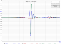
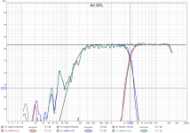
I made real life measurements from listening position with real speakers. Filters where linear phase LR48 at 2700 kHz for Hing pass and low pass, no other filters, just speaker elements as they are, only acoustical radiation center displacement compensation delay and level compensation (not in rePhase FIR filter) where involved.I think you are missing the forest for the trees here
I see nearly no ringing cancellation at all. Impulses are not normalized to get all in same scale.
Yes I know ringing here is very short and not audible, but to avoid room influence I not made measurements with bass and mid speakers, there will be 10 times longer ringing.
Attachments
Your crossover does not look to sum correctly. Generate a textbook version of the slope you want to achieve and compare it against the measured one. Add EQ until you get a closer match which should result in a good sum then you can see if it worked better.
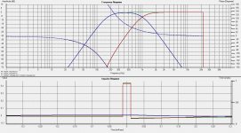
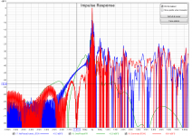
I made real life measurements from listening position with real speakers. Filters where linear phase LR48 at 2700 kHz for Hing pass and low pass, no other filters, just speaker elements as they are, only acoustical radiation center displacement compensation delay and level compensation (not in rePhase FIR filter) where involved.
I see nearly no ringing cancellation at all. Impulses are not normalized to get all in same scale.
Yes I know ringing here is very short and not audible, but to avoid room influence I not made measurements with bass and mid speakers, there will be 10 times longer ringing.
POS's advice in #3317 has always worked best for me.
That being, to disregard the impulse response and work with the frequency response.
When both mag and phase are flat, the impulse response will be spot on.
And just becomes another form of conformation of good tuning.
It's sooooo much easier to discern what to correct, working with frequency response (again, mag and phase)
I repost this, 4 days left before the release, feedback and bug reports welcome.
Listening Conditions is nice!
So much less work that stringing together a bunch of shelving filters, which has been my technique.
Your crossover does not look to sum correctly. Generate a textbook version of the slope you want to achieve and compare it against the measured one. Add EQ until you get a closer match which should result in a good sum then you can see if it worked better.
A good way to get this is to use a compensate of the target filter, apply whatever correction is needed to get a flat response, and remove the compensate filter.
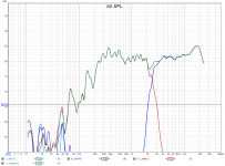
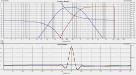
I made corrections to fit slopes better, I include to tweeter HP LR24 on 173 Hz what is approximate mid range HP natural acoustic filter, but not get any real ringing cancellation. I get less post ringing with compensations, but no pre ringing cancellation.Your crossover does not look to sum correctly. Generate a textbook version of the slope you want to achieve and compare it against the measured one. Add EQ until you get a closer match which should result in a good sum then you can see if it worked better.
On FR image with black are displayed FR of filters without EQ compensations made with rePhase.
Attachments
You might be mistaken at what to look for here.
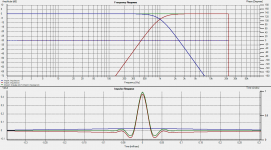
To see what IR target you should obtain you can try generating some textbook responses in rephase and see what the impulses look like.
One with that 173Hz hi pass and 1kHz low pass, and a second one with the 1kHz+173Hz hi pass.
Summing the two in REW should give you the same impulse as a 173Hz hi pass with no 1kHz low pass.
You might also want to include the 20kHz+ low pass as it might get you some visible (yet inaudible) ringing.
Last edited:
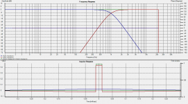
Now to wrap this up, let's go back to the same summation with the 173Hz hi pass, without interpolation.
There you see the preringing is gone, and all that is left is the post ringing of the minimum-phase hi pass.
This is the sample theory for you 🙂
There you see the preringing is gone, and all that is left is the post ringing of the minimum-phase hi pass.
This is the sample theory for you 🙂
Attachments
Last edited:
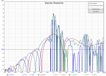
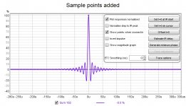
Turning the interpolation off in Holm is a good way of showing what is happening. I was trying to do the same thing myself in REW but if that function exists I haven't found it. What you can do is display sample points to see where the data is which looks like this

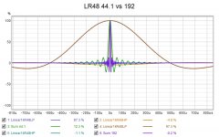
Here is an overlay of the difference between Linear Phase LR48 at 1k made at 44.1 and 192K. You can see the difference in the look of the impulse that the ringing displayed through the interpolation has changed and that the peak is narrower from the increased bandwidth and closer sample points. So I think how the impulse is displayed has a lot to do how much "ringing" there seems to be even though the samples underneath are the same.

Here is an overlay of the difference between Linear Phase LR48 at 1k made at 44.1 and 192K. You can see the difference in the look of the impulse that the ringing displayed through the interpolation has changed and that the peak is narrower from the increased bandwidth and closer sample points. So I think how the impulse is displayed has a lot to do how much "ringing" there seems to be even though the samples underneath are the same.
Attachments
Here is a paper where the development of a gaussian filter is discussed along with the effects of crossover filters and polar characteristics. Lots of maths but pretty pictures at the end to help it make more sense 🙂
https://www.researchgate.net/profile/Malcolm-Hawksford-2/publication/269101794_DIGITAL-CROSSOVER_DESIGN_STRATEGY_FOR_DRIVE_UNITS_WITH_IMPAIRED_AND_NON-COINCIDENT_POLAR_CHARACTERISTICS/links/58986f6fa6fdcc32dbdcfb83/DIGITAL-CROSSOVER-DESIGN-STRATEGY-FOR-DRIVE-UNITS-WITH-IMPAIRED-AND-NON-COINCIDENT-POLAR-CHARACTERISTICS.pdf
https://www.researchgate.net/profile/Malcolm-Hawksford-2/publication/269101794_DIGITAL-CROSSOVER_DESIGN_STRATEGY_FOR_DRIVE_UNITS_WITH_IMPAIRED_AND_NON-COINCIDENT_POLAR_CHARACTERISTICS/links/58986f6fa6fdcc32dbdcfb83/DIGITAL-CROSSOVER-DESIGN-STRATEGY-FOR-DRIVE-UNITS-WITH-IMPAIRED-AND-NON-COINCIDENT-POLAR-CHARACTERISTICS.pdf
To pos and fluid.
I made ringing cancellation test with cookbook complimentary filters in software already before my measurements. With theoretical cookbook complimentary filters ringing cancellation is present, no doubt.
My point is that in real life, with real speakers and room, it is nearly impossible to get this ringing cancellation even if real speaker element resulting filters are compensated to be very close to cookbook filter slopes.
For example in my case I had MTM type midrange-tweeter section, midrange is OB on triangular baffle, what in my opinion make mids not very minimal phase type. I had no identical amplifiers feeding the mids and tweeters, amplifies had different LP and HP cutting points. Also my tweeter is ribbon type with transformer and DC blocking capacitor with Fc about 1300 Hz. This all brings more different IR in series what all disturb ringing cancellation.
With my speakers I find also that audible ringing is much bigger in stereo than with left or right speaker alone. Probably in stereo is possible also ringing amplification of summary response from left and right.
Any response variation (delay, filter, etc.) caused by any element in the chain (DAC, amplifier, box, driver, etc.) absolutely needs to be taken into account and compensated for when building the correction.
Now if you find you cannot compensate for some aberrations, or your compensations do not hold throughout the listening window, then it is either a measurement or a design problem.
It has been my experience that with a proper design and proper measurements (emphasis on the "s") it is surprisingly easy to get close to textbook responses over the intended frequency range.
Proper design includes good directivity matching and small enough distance between drivers, drivers showing low breakup or resonance behavior, decent diffraction/reflection handling, etc.
Last edited:
Would it be easier to achieve with filters what had no pre ringing by nature, then also no ringing cancellation and bands IR precise match is not needed?
Not sure I exactly get what you mean, but looking at the frequency response and the impulse give you the same information. You can disregard the impulse in most cases, the frequency response being much more revealing and less confusing: simply try to get matching/tracking phase shift between drivers, and ignore the impulse altogether.
If you (virtually) get each driver's phase and magnitude flat in and around the passband (using compensate filters), and add linear-phase complementary filters, then summation is as easy as dialing the proper delay.
That is the method I recommend: https://www.diyaudio.com/forums/mul...ion-eq-fir-filtering-tool-68.html#post4322701
This is *much* easier than building a minimum-phase filter, especially if more than 2 ways are to be used, but of course this requires having access to a multiway convolution engine...
Aah yes okay okay 🙂 🙂
Now I just have one really stupid question
So when you say complementary crossover...... are you talking about
Using the same crossover topology (slope and alignment) on the low pass and high pass.....?? OR are you talking about using the same topology on the low and hi pass , in a bandpass filter? Or both?
I know it’s a really dumb question but I just want to make sure that I’m on the same page....
Complementary hi and low pass filter will sum to get a flat on axis response, with a known off axis behavior. Think about it as a seamless crossover.
All that is left on axis is an allpass in the case of a minimum-phase crossover.
A typical example of such a crossover is a LR, where both drivers are in phase throughout the crossover (phase tracking) and at -6dB at the crossover point.
Another example is an odd order Butt where phase is still tracked but 90° apart, and both drivers crossing at -3dB.
Both give a flat on axis response, but a different off axis behavior: different trade offs for different situations.
With FIR you can manipulate many other types of complementary filters, such as reject hi/low, Horbach-Keele, brickwall, overlapping filters, etc.
Of course in all cases, what matters is not the electrical filter alone, but the final filter that encompass the natural response of the driver/box and the electrical filter.
Probably not easier, but potentially less harmful if not set properly.Would it be easier to achieve with filters what had no pre ringing by nature, then also no ringing cancellation and bands IR precise match is not needed?
As a side note, minimum-phase and linear-phase filters do have the exact same amount of ringing for a given slope, the only difference is how that energy is spread around the peak. As such, minimum-phase filters post-ringing also cancels out when properly summed in a crossover.
When re-tuning speaker filters, I find rePhase is missing one function, transfer (export-import) of phase EQ setting from one filter set to other in way as now is possible import REW Gain EQ settings.
Or is this possible some how in current version?
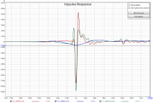
I find that if in clean flat filter I make phase tuning based on measured phase response, resulting IR have opposite pre and post ringing with system IR for what I made phase tuning, so somthing like ringing canceling is happening.
Is this just coincident or there is existing some mathematical background what make this kind of ringing canceling possible?
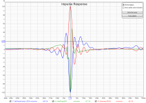
This is real IR measurements from my speaker with no phase tuned FR, phase tuning filter IR from reFhase FIR and measured summary when phase tuning FIR filter is applied. I see good ringing cancelling here.
Or is this possible some how in current version?
I find that if in clean flat filter I make phase tuning based on measured phase response, resulting IR have opposite pre and post ringing with system IR for what I made phase tuning, so somthing like ringing canceling is happening.
Is this just coincident or there is existing some mathematical background what make this kind of ringing canceling possible?
This is real IR measurements from my speaker with no phase tuned FR, phase tuning filter IR from reFhase FIR and measured summary when phase tuning FIR filter is applied. I see good ringing cancelling here.
Attachments
Last edited:
- Home
- Design & Build
- Software Tools
- rePhase, a loudspeaker phase linearization, EQ and FIR filtering tool