I have gone the ultra multiway way for the last 15 years so discussion like this, RePhase and REW has helped me a lot. Still think it is possible to find a compromise of
*latency
*Lowest membrane movement outside band, eg harmonic distortion outside limits of hearing
*Of/off axis frequency response
*Phase distortion inside the limits of hearing
*Artifacts, that is annoying sounds not related to the above
Of course it is a little worying that JBL M2, that is measured at 1000 points, is a 2 way🙂
I don't care about latency, I just press play a little sooner 😀.
No seriously, only reason for me to worry about latency would be movies, but with JRiver I can keep them synchronised. It's pure home entertainment, not any live shows for me. 😉
No seriously, only reason for me to worry about latency would be movies, but with JRiver I can keep them synchronised. It's pure home entertainment, not any live shows for me. 😉
@wesayso, thanks, generous helpful tutorial
@sax512, advice taken
FWIW,the way i go about removing ripples really doesn't have anything to do with the impulse response.
My tuning technique is to go driver by driver, getting magnitude and phase as flat and zeroed as possible, thru each driver's bandwidth and as far out of band as is necessary/reasonable to combine.
Then, using complementary linear phase crossovers, it is simply a matter setting of physical time offsets and level adjustments, to put it all together.
Using a real time dual FFT like smaart allows phase traces to pinpoint correct timing alignments very easily.
I never even look at an impulse response while tuning, for me it is a post tuning measurement more for verification, than anything else.
The flatter mag and phase look, the better the resulting impulse....
Just my technique...many ways to skin this cat..🙂
Then you are in good company linarizing the drivers first.
http://www.grimmaudio.com/site/assets/files/1088/speakers.pdf
From
LS1 | GrimmAudio
But looks like they are carefull with timeresponse and sharp filters. Maybe too careful, I hope.
http://www.grimmaudio.com/site/assets/files/1088/speakers.pdf
From
LS1 | GrimmAudio
But looks like they are carefull with timeresponse and sharp filters. Maybe too careful, I hope.
@wesayso, thanks, generous helpful tutorial
@sax512, advice taken
FWIW,the way i go about removing ripples really doesn't have anything to do with the impulse response.
My tuning technique is to go driver by driver, getting magnitude and phase as flat and zeroed as possible, thru each driver's bandwidth and as far out of band as is necessary/reasonable to combine.
Then, using complementary linear phase crossovers, it is simply a matter setting of physical time offsets and level adjustments, to put it all together.
Using a real time dual FFT like smaart allows phase traces to pinpoint correct timing alignments very easily.
I never even look at an impulse response while tuning, for me it is a post tuning measurement more for verification, than anything else.
The flatter mag and phase look, the better the resulting impulse....
Just my technique...many ways to skin this cat..🙂
You've shown excellent results and made sure not to include the room in measuring. 🙂
Have you ever confirmed the result at the listening position? Maybe I asked before. But if you do listen at different distances than designing it would be worth it to do a sanity check. 🙂
Last edited:
You've shown excellent results and made sure not to include the room in measuring. 🙂
Have you ever confirmed the result at the listening position? Maybe I asked before. But if you do listen at different distances than designing it would be worth it to do a sanity check. 🙂
Thx! Yes, indoors I measure the mains up close at about 1.5 meters just to help drown out reflections. Outdoors, I measure at about 3 meters because I have built a swinging boom mic rig off a deck to make measurements quick and easy. The measurements of course vary a little in the timing of the mid section to the CD coax. Outdoors is slightly best. But it's a pretty minor difference, the CD coax which goes down to 650Hz doesn't vary, and dang if I can hear the mains tuned one way vs the other. Really, tying the subs in is by far my dominating sonic challenge. When I do that outdoors, it's usually at 10m.
I don't listen in a sweet spot very much. Most my audio life i was into electrostats that demanded I sit like a statue...glorious sound for sure...but now my whole house rocks haha. Some songs sound better imaged to the sweet spot, some sound better two rooms away. I never know...🙂
Then you are in good company linarizing the drivers first.
http://www.grimmaudio.com/site/assets/files/1088/speakers.pdf
From
LS1 | GrimmAudio
But looks like they are carefull with timeresponse and sharp filters. Maybe too careful, I hope.
Yes, their paper makes total sense to me...other than they have better ears than me to hear sharp filters 🙂
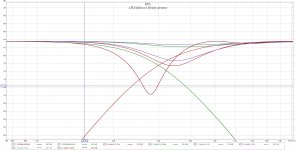
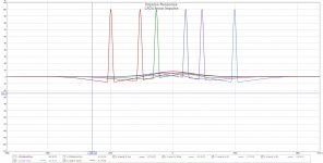
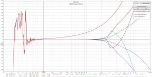
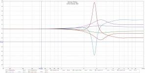
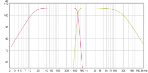
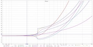
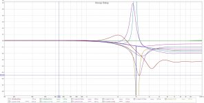
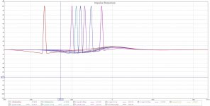
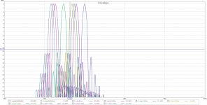
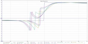
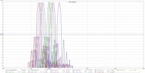
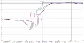
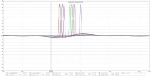
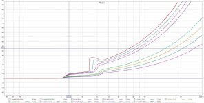
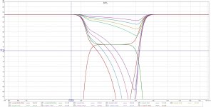
Just tried to shift the HP section of a LP/HP 3k LR linear phase filters.
Don't think it is artifacts🙂
But shifting up to +/- 0.2 ms really shake up the responces.
Even 0.05 ms, that is 1.5 cm dampens 1 dB.
Think the pictures are pretty self explanatory
Don't think it is artifacts🙂
But shifting up to +/- 0.2 ms really shake up the responces.
Even 0.05 ms, that is 1.5 cm dampens 1 dB.
Think the pictures are pretty self explanatory
Attachments
Just tried to shift the HP section of a LP/HP 3k LR linear phase filters.
Don't think it is artifacts🙂
But shifting up to +/- 0.2 ms really shake up the responces.
Even 0.05 ms, that is 1.5 cm dampens 1 dB.
Think the pictures are pretty self explanatory
Sure, 0.2ms is huge at 3k. I mean, 3k period is 0.33 ms, so @ .2ms you have 216 degrees of phase misalignment. Don't even need pictures, it's gonna suck !🙂
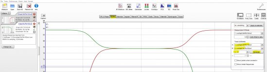
Year very frq point plus design of polar and spacing dependent 🙂 down at 500Hz with a steep LR 96dB/oct linear phase 0,05mS is not visible other than small blob in phase.
Attachments
Last edited:
Year very frq point plus design of polar and spacing dependent 🙂 down at 500Hz with a steep LR 96dB/oct linear phase 0,05mS is not visible other than small blob in phase.
Hi BYRTT, yep.
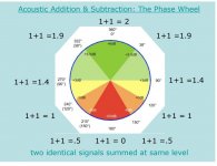
I really like to keep it intuitive....so I say ok, 0.05 ms divided by 2ms (period of 500Hz) X 360 deg = phase rotation = 9 deg
Then I compare degree rotation to phase wheel summation to know what to expect.... ....https://engineering.purdue.edu/ece40020/LectureNotes/Chapter_2.pdf
Attachments
Sorry, all, that was embarassing! Thank you mark100.
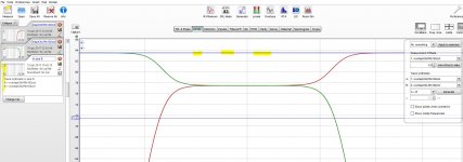
Enclose pictures what happens when going through the suckuot of inverted phase. -180degrees
Adjusted 1 and 1 sample, that is about 0,011ms or 4 mm distance.
Think I have been to sloppy on placing my tweeter when setting up quick prototypes.
Enclose pictures what happens when going through the suckuot of inverted phase. -180degrees
Adjusted 1 and 1 sample, that is about 0,011ms or 4 mm distance.
Think I have been to sloppy on placing my tweeter when setting up quick prototypes.
Attachments

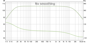
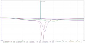
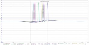
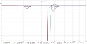
Tried 48dB/oct overlap and 192dB/oct overlap (next post) also.
Went from 0 to 180 degres out of phase of the two filters by introducing a delay on the HP filter.
Made more simulations in the transitions from small to large SPL deviations and round 180 degrees
3k Hz that is about 11 cm wavelangth and period of about 330 uS.
So 180 degrees out of phase is about 55 mm path difference, 165uS delay
At about 63 uS delay the SPL is -3 dB down, about 20 mm path difference.
I set 96k sampling so one sample is about 10uS or 3.4 mm
So it is only 6 samples delay before we are down at -3dB
Not sure about the real benefit of looking at the step responce, but a amplifier designer would worry if he had these amounts of ripple. Of course no stability issues here🙂
Attachments
-
 Overlap48dbREWETC.jpg339.6 KB · Views: 100
 -
 Overlap48dbREWStep.jpg265.6 KB · Views: 105
 -
 Overlap48dbREWGD.jpg216.8 KB · Views: 98
 -
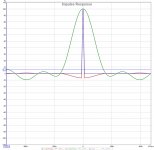
 Overlap48dbREWImpulse.jpg246.6 KB · Views: 116
 -
 Overlap48dbREWPhase.jpg298.9 KB · Views: 111
 -
 Overlap48dbREWSPL.jpg313.3 KB · Views: 114
 -
 rephaseOverlap3k.jpg274.1 KB · Views: 95
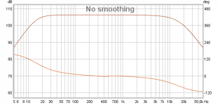
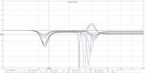
At 192db/Oct the inverted phase GD is extreme in a very small band, where the SPL is way down. Maybe artifacts at special material? (Artifacts: I mean noise or 'unrelated' sounds).
Wonder what happens with cabinet diffractions with that kind of group delay?
Inside dalay window, with accepteble deviation in SPL, the GD looks OK.
To me it looks like the window is larger (a samle more of delay) at 192db/oct. But when it gets bad it really gets bad.
Wonder what happens with cabinet diffractions with that kind of group delay?
Inside dalay window, with accepteble deviation in SPL, the GD looks OK.
To me it looks like the window is larger (a samle more of delay) at 192db/oct. But when it gets bad it really gets bad.
Attachments
-
 Overlap192dbREWETC.jpg346.9 KB · Views: 101
 -
 Overlap192dbREWStep.jpg279.1 KB · Views: 104
 -
 Overlap192dbREWImpulse.jpg247.8 KB · Views: 95
 -
 Overlap192dbREWPhase.jpg313.2 KB · Views: 113
 -
 Overlap192dbREWSPL.jpg298.6 KB · Views: 106
 -
 Overlap192dbREWGDfine.jpg221.5 KB · Views: 105
 -
 Overlap192dbREWGD.jpg242.7 KB · Views: 106
Last edited:
Hi torgeirs, I'm missing why we want to look at delay variations to begin with....
I mean, there is an on-axis time offset, at a given distance from the speaker, that simply represents a little bit of trigonometry aligning acoustic centers.
Choose your alignment distance and you get what you get ....nothing can be improved upon past that.... can it ??? (This is assuming a complementary linear phase crossover properly phase aligned.)
Last edited:
Yes, you are right for one ear at one place in space, (in a aneoic chamber)
* Some want to walk around while listening or has very unsymmetric listening distances for all listeners. Like car, home cinema for more than one or control room with more people.
* Reflected sound also give a signature to the speaker. Jbl, for example, measures 1000 points around the speaker.
So filter choise affect that off axis sound greatly. I'm interested in steep slopes and still ok off axis responce, has started to doubt, but hoping to find a solution.
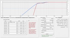
REW:
Import impulseresponses.
Convolution in time = multiplying in frequency = adding in dB in frequency
So adding the SPLs together (actually SPL AND phase) will be the same as convolving the time responses.
Then I guess you can export the new impulse response.
The pictures explaines the steps better.
There might be some issues with windows for very short filters.
Attachments
- Home
- Design & Build
- Software Tools
- rePhase, a loudspeaker phase linearization, EQ and FIR filtering tool