A 50 V peak-peak, 0.05 Hz ripple on a 5250 V high voltage supply should make the volume go up and down by a bit less than 1 %, or 0.08 dB, every 20 seconds.
You might be right.
I fed one of my Quad 63 with a sine of 1.5kHz. In order to enhance the S/N ratio of the measurement, I added some matching DSP peak filtering set at 1.5kHz at the mic's input. While measuring, the neon bulb was flashing at a rate of every 33 seconds plus/minus. The -0.25dB notch at 00:01:40 is an erratic soundcard output signal artefact.
Last edited:

How close was your microphone?
Impressive... good work!
No need to filter that HV bias I guess 😎
Impressive... good work!
No need to filter that HV bias I guess 😎
Impressive measurement confirmation of a subtle effect! Thanks for Sharing
Another less known fact is that sustained LF tones near the diaphragm resonance frequency will increase the sensitivity of the ESL by a measurable amount.
From the Baxandall ESL chapter a plot shows roughly 0.4dB increase from 7Vrms input.
Text mentions that the sensitivity increase effect is proportional to the square of the LF tone magnitude.

Reference:
P. J. Baxandall, “Electrostatic Loudspeakers,” Chapter 3 in Loudspeaker and Headphone Handbook, J. Borwick, Ed.
(Reed Educational and Professional Pub., Woburn, MA,
1998), pp. 106–195.
Another less known fact is that sustained LF tones near the diaphragm resonance frequency will increase the sensitivity of the ESL by a measurable amount.
From the Baxandall ESL chapter a plot shows roughly 0.4dB increase from 7Vrms input.
Text mentions that the sensitivity increase effect is proportional to the square of the LF tone magnitude.
Reference:
P. J. Baxandall, “Electrostatic Loudspeakers,” Chapter 3 in Loudspeaker and Headphone Handbook, J. Borwick, Ed.
(Reed Educational and Professional Pub., Woburn, MA,
1998), pp. 106–195.
Last edited:
...How much does the bias have to change for a 1dB sensitivity change, is it a linear law (1dB being ~12%)?

Yes it is a linear law. Looking at the Force Equation above(from Baxandal ESL chapter), the sensitivity is directly proportional to the bias voltage and applied signal voltage.
So dB(Change) = 20*LOG[ Vbias(new) / Vbias(reference) ]…as you say changing the bias voltage by ~12% produces a 1dB change.
A plot comparing measurement and theory for bias voltage change from an old thread:
https://www.diyaudio.com/community/...nance-change-with-hv-bias.147801/post-2378013

Note the other term in the Force equation is the negative compliance or stiffness which is proportional to the square of the bias voltage.
Quad designed the ESL63 panels such that the mechanical tension is roughly 3.5x larger than the negative stiffness.
Running thru the math for the ESL63 and a ~12% change in the 5.25kV bias voltage, the diaphragm resonance frequency will change about 5%.
Increasing bias voltage results in resonance frequency decreasing.
If interested in negative compliance, here are some related posts:
https://www.diyaudio.com/community/threads/electrostats-vs-conventional-drivers.17424/post-6957351
https://www.diyaudio.com/community/threads/current-vs-voltage-drive-esl.175918/post-2366501
https://www.diyaudio.com/community/...nance-change-with-hv-bias.147801/post-1884466
Reference:
P. J. Baxandall, “Electrostatic Loudspeakers,” Chapter 3 in Loudspeaker and Headphone Handbook, J. Borwick, Ed.
(Reed Educational and Professional Pub., Woburn, MA,
1998), pp. 106–195.
@jan.didden
Jan, are you sure about the supposed bias-voltage drop in more recent models.
It’s interesting that none of the above experts, although dealing with ESL’s almost on a daily basis, could confirm this so far.
Hans
Jan, are you sure about the supposed bias-voltage drop in more recent models.
It’s interesting that none of the above experts, although dealing with ESL’s almost on a daily basis, could confirm this so far.
Hans
There was a mention in the lit years ago about needing to lower the bias for altitude and also relating to humidity. The details are deep in fuzzy history but were a specific issue. I thin it relates to the breakdown voltage of air which both humidity and altitude affect. Quad may have decided to lower all production to eliminate location specific versions.
And the modulation from LF content is something to not completely ignore. At least it validates the 100 Meg resistors we added to each panel's bias connection on the Crosby mod along with the stabilized HV supply.
And the modulation from LF content is something to not completely ignore. At least it validates the 100 Meg resistors we added to each panel's bias connection on the Crosby mod along with the stabilized HV supply.
Demian, I wonder how that LF modulation could be measured?
I have a unit instrumented for direct measurement at the stators (thanks to your HV resistors!).
Jan
I have a unit instrumented for direct measurement at the stators (thanks to your HV resistors!).
Jan
You probably mean that the charge on the resp. diaphragms may be modulated by the LF signal.There was a mention in the lit years ago about needing to lower the bias for altitude and also relating to humidity. The details are deep in fuzzy history but were a specific issue. I thin it relates to the breakdown voltage of air which both humidity and altitude affect. Quad may have decided to lower all production to eliminate location specific versions.
And the modulation from LF content is something to not completely ignore. At least it validates the 100 Meg resistors we added to each panel's bias connection on the Crosby mod along with the stabilized HV supply.
But will the Bias Voltage be modulated also?
And if so, could a 100Meg resistor play any role in reducing this bias voltage modulation ?
Hans
The way I see it, there are two sides on the bias.
One is a stable, possibly regulated, outout for loudness consistency versus mains variations and such.
The other is the possible mains ripple. I would think the latter is moot what with the very low current draw and the high RC value connected to the output.
Jan
One is a stable, possibly regulated, outout for loudness consistency versus mains variations and such.
The other is the possible mains ripple. I would think the latter is moot what with the very low current draw and the high RC value connected to the output.
Jan
Jan,
Mains variations have no impact at all because of the VDR’s inside the bias generator, see red line in #576’s image where you measured a secondary 640Volt, far on the right side of the graph.
And the 1.5V mains induced ripple on the 5k25V bias is nothing compared to the 50Volt relaxion curve caused by the neon bulb.
Shorten the neon bulb when in doubt whether this has a negative impact on sound perception.
When it doesn’t, you can forget the 1.5Volt mains ripple IMO.
Hans
Is there a halfway house?
Bypass the neon with a 'modest value' resistor c 4M7; once the panel is up to voltage, the neon never lights, but the TC with the 47nF cap is well sub-audio.
Lightbulb!: now I see why 100M was suggested above...
<curious bystander here/>
Bypass the neon with a 'modest value' resistor c 4M7; once the panel is up to voltage, the neon never lights, but the TC with the 47nF cap is well sub-audio.
Lightbulb!: now I see why 100M was suggested above...
<curious bystander here/>
And the 1.5V mains induced ripple on the 5k25V bias is nothing compared to the 50Volt relaxion curve caused by the neon bulb.
Shorten the neon bulb when in doubt whether this has a negative impact on sound perception.
When it doesn’t, you can forget the 1.5Volt mains ripple IMO.
Hans
There are many differences:
1.5 V is less than 50 V
50 Hz will be filtered by the diaphragm resistance and capacitance, while 0.02 Hz will not (or hardly, to be precise)
Masking of sidebands at 0.02 Hz frequency offset will be stronger than at 50 Hz frequency offset
Then again, a 0.02 Hz triangle wave has lots of higher harmonics.
Demian, I wonder how that LF modulation could be measured?
I have a unit instrumented for direct measurement at the stators (thanks to your HV resistors!).
Jan
Isn't that explained in post #584, or is this some other issue?
It’s not even a triangle but a sawtooth at 0.02Hz with a very sharp slope with lots of harmonics and the 50Hz ripple is not a nice sinus shaped signal but also one with lots of harmonics.There are many differences:
1.5 V is less than 50 V
50 Hz will be filtered by the diaphragm resistance and capacitance, while 0.02 Hz will not (or hardly, to be precise)
Masking of sidebands at 0.02 Hz frequency offset will be stronger than at 50 Hz frequency offset
Then again, a 0.02 Hz triangle wave has lots of higher harmonics.
And yes, the higher the frequency, the greater the frequency offset caused by these unwanted harmonics.
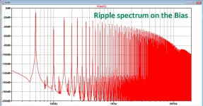
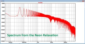
To get a feeling about what we are talking about, good old LTSpice can give us more insight.
The Neon relaxation will give a contribution in the audio range that's indeed below the 50Hz induced ripple on the bias, see below.
I'm surprised how slow the decay of al the harmonics on the Bias is, so Demian might be right that a tightly regulated Bias voltage may be produce a cleaner sound.
Sorry Demian for not having believed this as being a possible improvement.
Hans
Attachments
I indeed meant sawtooth, but wrote triangle. Silly me.
Please keep in mind that your simulation doesn't include the frequency conversion that you get due to the multiplication with the desired signal, nor the filtering due to the distributed resistance and capacitance of the diaphragm.
Please keep in mind that your simulation doesn't include the frequency conversion that you get due to the multiplication with the desired signal, nor the filtering due to the distributed resistance and capacitance of the diaphragm.
I simulated the bias ripple spectrum and not the signal's AM modulation due to multiplication, but it's obvious that the wider the spectrum the farther the modulated sidebands are from the audio signal and the more likely it becomes that it can be perceived.
But including the capacity that the diaphragm is facing is a good idea.
See simulation below.
When loading the bias with a 2nF cap, difference is only a few dB's.
Hans
But including the capacity that the diaphragm is facing is a good idea.
See simulation below.
When loading the bias with a 2nF cap, difference is only a few dB's.
Hans
Attachments

Gents, just a quick one: in the ESL63 input circuit there is a resistor in series with each transformer secondary, specified as '2 x 3.3' .
Is that series or parallel?
Jan
Is that series or parallel?
Jan
They must be in parallel; some schematics say "R1 ab 1R65" and "R2 ab 1R65". They are in series with the primary windings of the step-up transformers.
- Home
- Loudspeakers
- Planars & Exotics
- QUAD 63 (and later) Delay Line Inductors