Yes Hans, I found it in your model.
A follow up question: I looked at the 1.5R//220uF at the primary.
I wonder what the purpose is, is it a measure of protection for the driving amplifier, to avoid too low impedance at the LF end,
or is it to correct the speaker response?
That response gets much flatter if the R is deleted (and also the elcap of course)
I do my correction with Acourate and would like to get rid of that electrolytic if feasible.
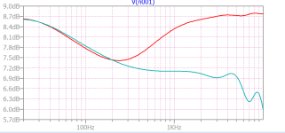
RED with 220u // 1.5, TEAL with 1nF // 1.5
Edit: Hans, there's a 1.5uF cap across the two primaries in your sim, what does that represent?
Jan
A follow up question: I looked at the 1.5R//220uF at the primary.
I wonder what the purpose is, is it a measure of protection for the driving amplifier, to avoid too low impedance at the LF end,
or is it to correct the speaker response?
That response gets much flatter if the R is deleted (and also the elcap of course)
I do my correction with Acourate and would like to get rid of that electrolytic if feasible.
RED with 220u // 1.5, TEAL with 1nF // 1.5
Edit: Hans, there's a 1.5uF cap across the two primaries in your sim, what does that represent?
Jan
Attachments
Last edited:
Jan, the 1.5R resistor should limit the current through the transformers at LF that could cause the transformers go into saturation.
When you simulate the model, you will notice this.
The 1.5uF across the transformers that Quad inserted is to correct the impedance at HF.
Hans
When you simulate the model, you will notice this.
The 1.5uF across the transformers that Quad inserted is to correct the impedance at HF.
Hans
See what the current does without the 1,5R when putting a 10Hz signal on the transformers, clearly showing the saturation.

Hans
Hans
Thanks Hans, that's clear!
I think I will leave it out as I plan to cross over at about 200Hz not using the bass panels.
I don't see that 1.5u at the QUAD factory drawing from '89. Was that added at a later time?
Jan
I think I will leave it out as I plan to cross over at about 200Hz not using the bass panels.
I don't see that 1.5u at the QUAD factory drawing from '89. Was that added at a later time?
Jan
In '89 it was definitely there, I think it was always there, but not all circuit diagrams are complete.
Hans

Hans
Jan,
I forgot to mention in #603 that the blue line represents the transformer current for a low level 10Hz signal, already showing its non linearity at this frequency and that the teal curve is the current for a higher amplitude 10Hz input signal, suddenly showing these huge current peaks.
Hans
I forgot to mention in #603 that the blue line represents the transformer current for a low level 10Hz signal, already showing its non linearity at this frequency and that the teal curve is the current for a higher amplitude 10Hz input signal, suddenly showing these huge current peaks.
Hans
That was clear Hans. I didn't have this diagram, thanks for posting it.
BTW, I initially thought that 'C21 ab 20n' stood for 'about 20n'.
Now I know it's two parallel caps, C21a and b together being 20n.
Funny guy, Peter Walker 😎
Jan
BTW, I initially thought that 'C21 ab 20n' stood for 'about 20n'.
Now I know it's two parallel caps, C21a and b together being 20n.
Funny guy, Peter Walker 😎
Jan
Jan,
Looking in the partlist I see 6 pieces of 10nF capacitors for C18 to C23.
So to my belief he used 20nF caps in series to get this 10nF.
I may be wrong, but 10nF is the value I used in my simulation.
Hans
Looking in the partlist I see 6 pieces of 10nF capacitors for C18 to C23.
So to my belief he used 20nF caps in series to get this 10nF.
I may be wrong, but 10nF is the value I used in my simulation.
Hans

If you have a tube amplifier (with output transformer) you can shortcut the 1,5ohm resistor. and you can save a lot money on reduced amount of copper in the speaker cable. For demonstration i have used the thinnest wiring wires i could find just to prove how the sound changes between a supra 10mm2 speaker cable and 0,1mm2 wire. Spoiler alert... alway when I do this people prefer the thinnest wire 10/10 since it gives more output in LF, and we tend to like more bass.
Very confusing, in my (an official QUAD) schematic there are some 10nF that are in parallel to get 20nF.Jan,
Looking in the partlist I see 6 pieces of 10nF capacitors for C18 to C23.
So to my belief he used 20nF caps in series to get this 10nF.
I may be wrong, but 10nF is the value I used in my simulation.
Hans
I will check on a spare board I have somewhere.
Jan
Attachments
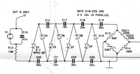
Two revisions of the HT Board from the Quad63 service manual: On ISS 2 caps are single, on ISS 3 twin caps are parallalled:

Mine, SN 023810 and 023809, have single caps:

Mine, SN 023810 and 023809, have single caps:
Last edited:
In the board I have there are a grand total of 14 caps, each 10nF/2kV, and several are in parallel to form the 20nF caps showed in the circuit in post # 611.
So that appears to jive with reality, both value and number of caps.
Jan
So that appears to jive with reality, both value and number of caps.
Jan
Sorry for the late reply. Yes, the probe has 100MOhm as it is built with 10x 10Mohm resistors, and I did try it with lower voltages (didnt measure the current though).
Maybe I should have mentioned that I measured the voltage directly at the output of the cascade, before the 10M resistor. This is with new components (diodes and caps) in the cascade.
I am a little doubtful of my measurement now, it should have been 5.25kV.... maybe I'll repeat the measurement. Speakers are playing fine 😀
As Hans mentioned before, in simulation, 100Meg maybe too much load and will lower the voltage.
We should find someone with an electrostatic HV meter.
I've been looking for one to buy but they are either expensive or old and decripit.
Demian probably has one?
On a positive note, I just took delivery of a Uni-T type 513A isolation tester.
Jan
We should find someone with an electrostatic HV meter.
I've been looking for one to buy but they are either expensive or old and decripit.
Demian probably has one?
On a positive note, I just took delivery of a Uni-T type 513A isolation tester.
Jan
My board looks exactly like the lower, Fig 17.
Jan
Funny guy, Peter Walker 😎
My board looks exactly like the lower, Fig 17.
Ghirlande ghirlande ... The layout of C-parallelization in Fig. 17 does neatly match your former statement about P.Walker ... assuming he was the designer of this board also. I think he must have been a really creative out-of-the-box thinker and enjoying amusing himself while designing.
Last edited:
FWIW, Quad is back in the US with their new 2812X electrostats. Heard them two weekends ago at the Capital Area Audiofest. Sounded lovely.
Kent McCollum, the most knowledgeable Quad guy I know says that from a panel longevity perspective, they are the best yet. With a three year panel warranty!. Kent's enthused enough that he may get out of the panel rebuilding business. Quad also added refinements and beefed up the construction to where it should have been in the first place. And dropped the price.
Kent McCollum, the most knowledgeable Quad guy I know says that from a panel longevity perspective, they are the best yet. With a three year panel warranty!. Kent's enthused enough that he may get out of the panel rebuilding business. Quad also added refinements and beefed up the construction to where it should have been in the first place. And dropped the price.
Interesting. I assume that's China production?
BTW A 3-year warranty on the panels doesn't seem useful, they alway fail at 10-years + ...
Do you know what they cost?
BTW2 Charles, missed you at this years' ETF!
Jan
BTW A 3-year warranty on the panels doesn't seem useful, they alway fail at 10-years + ...
Do you know what they cost?
BTW2 Charles, missed you at this years' ETF!
Jan
Last edited:
- Home
- Loudspeakers
- Planars & Exotics
- QUAD 63 (and later) Delay Line Inductors