But if it not too much trouble, receiving a 1 sec 1Khz .wav recording would be nice to compare
I have the feeling that this discussion does not make much practical sense. Maybe I am wrong. But how much ripple do you exactly expect? And which is your personal perception threshold for delta sound intensity? Mine is about 0.5dB. And therefore I am not able to perceive the much, much bigger SPL step (much much bigger than the ripple) when the neon flashes and the diaphragm is reloaded by some 20V ... 50V. Assuming we are talking of a ripple amplitude of some 1V ... 2V.
Last edited:
There's 47n // to the neon which will have to be discharged.
Do we know the dynamic impedance of an ignited neon?
Edit: it depends on current, it takes time for that cap to discharge and the 'step' in bias is not abrubt.
Hans do you have a sim model for that neon lamp?
Jan
Do we know the dynamic impedance of an ignited neon?
Edit: it depends on current, it takes time for that cap to discharge and the 'step' in bias is not abrubt.
Hans do you have a sim model for that neon lamp?
Jan
Attachments
Last edited:
So are you, and that's no joke.You're invited
How can you separate 50Hz coming from the audio chain from the 50Hz from the ESL ?
You are cordially invited to show this 50Hz on my system.
Hans
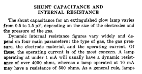
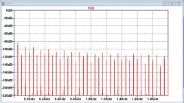
Here is the simulation I promised.
First image is the ripple's spectrum on the Bias voltage, for clarity from 0Hz to 2KHz on a linear scale and divided by 5000.
Second image is a 1Khz signal AM modulated by the (Bias Ripple)/5000.
You can see that the spectrum of the first image is mirrored on both sides of the 1Khz signal because of AM modulation.
This modulation in effect happens to all frequencies in the audio signal.
Can this be improved: yes certainly.
Does it lead to an improvement in sound perception: I can't say, but according to Demian it makes a big difference.
Hans
Attachments
Jan,There's 47n // to the neon which will have to be discharged.
Do we know the dynamic impedance of an ignited neon?
Edit: it depends on current, it takes time for that cap to discharge and the 'step' in bias is not abrubt.
Hans do you have a sim model for that neon lamp?
Jan
look at the sim where the neon bulb is visible, simulated as a switch closing at 100V and opening at 50V.
A NE-2 neon bulb draws between 100uA and 10mA, so a value of 1mA in the middle seems reasonable.
Tripping at 100Volt, that means a 100Kohm resistance.
In fact a neon bulb has a negative resistance, so the 100K is on the mild side.
In combination with the 47nF this gives roughly a discharge time from 100V to 50V of ca. 3msec.
Hans

Matching probe?? You are not looking for vibrating type. You want a classic electrostatic meter like these: Sensitive Research Model ESD If you have a stable reference HV supply you can uxse it to measure the difference.Works great and you get more resolution. At the vintage these are you should check the calibration.I have a couple of vintage Telefunken 5kV HV meters which I used in the development of the direct drive amp, but they draw up to 50uA.
I contacted several eBay sellers that offer reasonably priced and undamaged electrostatic voltmeters, but none have the matching probe available.
Jan
Demian, the meters I found at eBay mostly had a 4 or 5 pin connector for a probe.
I asked the sellers and they all said 'no probe', like this one.
I looked up that Sensitive Research meter and it has two connection terminals, 'low side or ground' and 'high side'.
So does that have to be connected to the circuit to be measured?
That's not electrostatic. Clearly I'm missing something.
Jan
Sorry, I misunderstood.So are you, and that's no joke.
How can you separate 50Hz coming from the audio chain from the 50Hz from the ESL ?
You are cordially invited to show this 50Hz on my system.
Hans
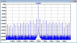
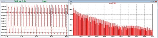
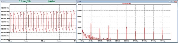
To get a better feeling to what a higher input frequency does for feeding the Bias Generator, I simulated both 50Hz and 50Khz.
Quite obvious for every frequency increase by a factor 10, the time signal and spectrum both drop by 20dB.
So a factor 1000 show's a time signal and spectrum that's 60dB lower, apart from the fact that 50Khz is completely outside the audio spectrum.
The left side of the two images shows the signal versus time, while at the right it's corresponding spectrum is visible.
The time signal changes it's shape at 50Khz, but the spectrum still looks very much like at 50Hz.
It seems like an interesting modification that Braun performed for the LE1.
Hans
Attachments
Jan:Demian, the meters I found at eBay mostly had a 4 or 5 pin connector for a probe.
I asked the sellers and they all said 'no probe', like this one.
I looked up that Sensitive Research meter and it has two connection terminals, 'low side or ground' and 'high side'.
So does that have to be connected to the circuit to be measured?
That's not electrostatic. Clearly I'm missing something.
Jan
The Trek meters are for measuring charge on a surface, like a copier or laser printer. The Sensitive Research meter has what looks like a variable capacitor inside with one plate attached to the pointer. The applied voltage (AC or DC) pulls the plates together. The meter indicates the potential. The Wikipedia article is a pretty good explanation. One wire to each potential. The insulation resistance is almost unmeasurable (1 X 10e15). You just attach directly to the potential you are measuring, 100 Meg in series in the probe will have no effect. The hard part is finding a 6KV unit for Quads. The scales are non linear (and hand drawn on the SR instruments) so the range is limited. Here is one: https://www.ebay.com/itm/3045864528...xH2RwExstNqOLhdLWNelroK64=|tkp:Bk9SR7ahif7_Yg But it looks like it needs repair. Here s another thats pretty trick: https://www.ebay.com/itm/1138995426...jKh5Y0t6DekNwy8m2brQMZLQI=|tkp:Bk9SR_zYqv7_Yg
Hans, here is the full article from Burkhard. It's in German but Google translate is your friend.To get a better feeling to what a higher input frequency does for feeding the Bias Generator, I simulated both 50Hz and 50Khz.
Quite obvious for every frequency increase by a factor 10, the time signal and spectrum both drop by 20dB.
So a factor 1000 show's a time signal and spectrum that's 60dB lower, apart from the fact that 50Khz is completely outside the audio spectrum.
The left side of the two images shows the signal versus time, while at the right it's corresponding spectrum is visible.
The time signal changes it's shape at 50Khz, but the spectrum still looks very much like at 50Hz.
It seems like an interesting modification that Braun performed for the LE1.
Hans
He mentions, in passing, that he can hear the 50Hz bias hum especially in silent passages.
https://www.burosch.de/audio-technik-blog/758-le-1-hochspannungsversorgung.html
Jan
Demian, thanks for the clarification. This technology is a white spot in my knowledge base 😎
If I look at this https://www.ebay.com/itm/3045864528...xH2RwExstNqOLhdLWNelroK64=|tkp:Bk9SR7ahif7_Yg
the pointer looks like it is deformed/bent. Or do they all look like that?
Maybe I should just get one and play with it.
Jan
If I look at this https://www.ebay.com/itm/3045864528...xH2RwExstNqOLhdLWNelroK64=|tkp:Bk9SR7ahif7_Yg
the pointer looks like it is deformed/bent. Or do they all look like that?
Maybe I should just get one and play with it.
Jan
Jan, thx a lot.Hans, here is the full article from Burkhard. It's in German but Google translate is your friend.
He mentions, in passing, that he can hear the 50Hz bias hum especially in silent passages.
https://www.burosch.de/audio-technik-blog/758-le-1-hochspannungsversorgung.html
Jan
In tried in various ways with my ESL 63's, main amp off, main amp on without input-signal, main amp on playing a silent passage.
But in none of the cases I couldn’t hear any sign of a 50 Hz or harmonic.
No idea whether I still have 10nF or 20nF caps, but since my ESLs where made for Polygram as studio monitors, I guess they are probably 20nF.
But I noticed a big difference between the 57 and the 63 in the Bias Generator, being that two different Bias voltages are generated instead of just one and that 6KV Bias is used for the two bass panels, the ones that are probably causing the 50Hz hum.
Also don't know the bass panel's resistance, but maybe more current is flowing causing a higher ripple on the bias.
Maybe someone else can fill in the missing ESL 57 gaps and report on any signs of 50Hz hum on a ESL63.
Hans
Yes, apparently the '57 used only 1.5kV for the mid/high panel and 6kV for the bass panel.Jan, thx a lot.
In tried in various ways with my ESL 63's, main amp off, main amp on without input-signal, main amp on playing a silent passage.
But in none of the cases I couldn’t hear any sign of a 50 Hz or harmonic.
No idea whether I still have 10nF or 20nF caps, but since my ESLs where made for Polygram as studio monitors, I guess they are probably 20nF.
But I noticed a big difference between the 57 and the 63 in the Bias Generator, being that two different Bias voltages are generated instead of just one and that 6KV Bias is used for the two bass panels, the ones that are probably causing the 50Hz hum.
Also don't know the bass panel's resistance, but maybe more current is flowing causing a higher ripple on the bias.
Maybe someone else can fill in the missing ESL 57 gaps and report on any signs of 50Hz hum on a ESL63.
Hans
I'll ask Burkhard if he has an idea which of the panels had the hum.
Jan
From Burkhard:
I remember the following: sitting in a distance of 2m from each LS the four bass/mid panels (two per box) were the creators of hum (inputs of the LSs shorted). The two high panels, each located between two bass/mid panels, may have added hum too, however with a very much lower level because of their very much smaller size, thus, practically not exactly identifiable.
No audible hum was generated by the solid-state PA (with input shorted output SN better than -92 dBV or -97 dBV(A)) - LS input connected to PA output.
The new 50kHz PSU fully solved my problem.
Jan
Well, this seems to indicate that the ESL 63 without any sign of 50Hz hum, for whatever change in construction, is superior to the ESL 57
At the same time I don’t understand how a ripple on the bias with shorted audio input can lead to hum as Burkhard describes. Could it possibly be that this was a transformer hum transferred through the ESL’s structure and seemingly be generated by the panels ?
But, we still have the issue with the bias ripple Amplitude Modulation interfering with the sound, potentially in a perceivable way.
Demian, the only person so far, has mentioned that a ripple free bias makes a large improvement to the sound.
It would be nice to have more reactions.
Hans
I am implementing ripple-free bias but are several months away from listening sessions ...
The way I see it, if you short the audio input and the two stators are at absolutely zero volts, anything on the diaphragm including hum will be audible (if of sufficient level of course).
Everything is relative since 1916 😎
Edit: if the ESL63 is 'better' in this context it must have something to do with the diaphragm surface resistance me thinks.
Jan
Jan,
When putting a signal on the diaphragm, equal forces will pull on the diaphragm if both stators are having the same potential.
So in effect it won’t move and will not produce any sound, without a direct relation to surface resistance.
The diaphragm will only start moving when both stators are having different voltages and are because of that pulling with different forces.
Hans
- Home
- Loudspeakers
- Planars & Exotics
- QUAD 63 (and later) Delay Line Inductors