That’s what I also suggested in #538
??? Post #538 seems to be a post of Jan Didden's.
What happens with the 200Hz with shorted audio input
I measured now with the speaker inputs shorted, so no input signal. And the rest of the gear non-functional, switched off. Note the different kind of averaging, this time with some 40 linear averages. For ESL36 item no. 1 (left stereo speaker):
And this for it's stero right side sibling:
On the broader frequency scale now, another peak is emerging at 300Hz (and maybe another one in between 200Hz and 300Hz?) in this new measurement and averaging series. Besides these 200Hz/300Hz artefacts findings, nothing exciting. And especially no dirty 50Hz zone.
Then: Switch off the mains live connection at the speaker basis of the ESL63:
That’s what you get when typing too fast.
It should be #658.
Hans
It should be #658.
Hans
Could it possibly be that this was a transformer hum transferred through the ESL’s structure and seemingly be generated by the panels ?
Maybe try measuring close to the power supply in back to see if the 200 Hz is stronger. Transformers will radiate noise.

The good news is that while playing a soft signal at 0.283 Veff or ca. 0.02 Watt, absolutely no trace of AM is visible on the recorded 1.5 Khz down to -70dB.
So diaphragm edge problems can obviously be discarded for causing hum, AM and signal distortion.
Thx Daihedz for taking the time to make this recording.
The whole discussion arround an eventual problem was theoretically interesting but didn’t exist in real life.
No need to construct a 50Khz bias generator or inserting 100Meg resistors in series with the individual diaphragms.
Looking at the images that Daihedz showed, it reinforces my feeling that Burkhard was having trouble with a mechanically humming transformer that made the whole ESL 57 vibrate at or close to the panel’s fres.
Removing the transformer and replacing it by a 50 Khz circuit, solved the problem of this mechanical transformer hum transfer.
Hans
Last edited:
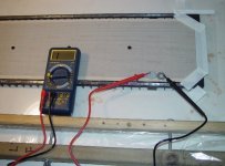
This is what I found on the internet concerning the diaphragm’s so called sheet resistance, which is the resistance of a square independant of the size of the square.
A value for this sheet resistance of 1Gig was mentioned for the coating applied by Quad.
Measuring could be done like in the image with two washers on top of the coating to prevent damaging the mylar film with the probes.
Hans
A value for this sheet resistance of 1Gig was mentioned for the coating applied by Quad.
Measuring could be done like in the image with two washers on top of the coating to prevent damaging the mylar film with the probes.
Hans
Attachments
Simple resistivity per square measurement tool.
http://www.benetechco.net/en/products/gm3110.html
http://www.benetechco.net/en/products/gm3110.html
Last edited:
Wout,
Am I correct that you are in the ESL repair business?
And is it correct that for each panel, both long sides of diaphragm are connected to a metal strip over their whole ca 60 cm lenght.
The panels are ca 15cm in height, so you can fit 4 squares in parallel on one diaphragm.
When sheet resistance would be 1Gig, the resistance between both opposite connection points would be 250Meg.
Does this make sense ?
Hans
That is my brother. I hop along.
On the long sides of the panels there are are aluminium strips that go over the length to about 5 cm from each side.
Don't know if you can calculate resistance per square into non square areas like you discribe.
Most factory ESL-63 panels have a surface resistance of about 50 Meg per square.
On the long sides of the panels there are are aluminium strips that go over the length to about 5 cm from each side.
Don't know if you can calculate resistance per square into non square areas like you discribe.
Most factory ESL-63 panels have a surface resistance of about 50 Meg per square.
Would it be possible for you to measure the resitance on a panel between the two aluminium strips ?
Hans
Hans
You are right, in theory it would be 1/4 of the resistance, but the coating is irregular since the production process is not that controlled.
And actually if you double or half the resistivity from a nominal value you will not be able to either hear or measure some difference.
When you change factor 10 there is a difference, especially if you go down in resistivity the distortion at low frequencies will be measurable. If you go active and cross over at 100 Hz there will obviously be less harm.
Yes you can measure between the strips, but there is no contact all the way between strip and membrane.
I recommend to coat the membrane at the edge with a more conductive compound, i have used graphite.
Since the metal strip only touches on small fractions of the membrane it is good to distribute the charge more easy. Especially if you use more modern coating with higher resistivity than original. (gives less distortion)
Remember to clean the stators from all conductive coating to reduce leakage quiescent currents.
During manufacturing process Quad applied such stuff in the form of a 5mm strip along the edges, corresponding to the aluminium band location. When I rebuilt my ESL63s this is what I used : https://www.agarscientific.com/media/import/AGG303_Jan14.pdfI recommend to coat the membrane at the edge with a more conductive compound, i have used graphite.
Thx for all interesting info’s concerning the coating.
But seemingly the sheet resistance must be quite a bit lower as 1Gig.
That makes the 10Meg in line with the Neon more understandable to prevent influence from the bias ripple on the diaphragm edges.
Hans
But seemingly the sheet resistance must be quite a bit lower as 1Gig.
That makes the 10Meg in line with the Neon more understandable to prevent influence from the bias ripple on the diaphragm edges.
Hans
You mean the Speaker model or the Bias generator?
In the speaker model the bias didn’t have to be included since sound production is direct proportional to the current through the caps.
The Bias generator model has not yet been finalised with the panel’s resistance.
That’s why I was asking.
But in general, the higher the sheet resistance, the more the Bias ripple filtering, but also the more the edge sensitivity to bias ripple with the 10Meg in series.
Hans
Remember that the colloidal suspended particles will settle over time... it will probably still work but the resistance may be 10 times higher. but still it will good enough.During manufacturing process Quad applied such stuff in the form of a 5mm strip along the edges, corresponding to the aluminium band location. When I rebuilt my ESL63s this is what I used : https://www.agarscientific.com/media/import/AGG303_Jan14.
Based on Wout’s measurements, I think the the sheet resistance is at the ca. 100Meg, altough it was not mentioned whether these panels still had the original Quad coating.
Hans
Hans
- Home
- Loudspeakers
- Planars & Exotics
- QUAD 63 (and later) Delay Line Inductors