Even with ideal "perfect" construction, the diaphragm will deflect to one side or the other due to minute random air currents or acoustic energy impinging on it. Once it starts moving off center, it will continue to deflect until the Force from the negative compliance term is balanced by the mechanical tension term. The deflection will take on a curved shape with larger charge content in the center where the diaphragm is closest to the stator. To solve the exact shape and deflection magnitude requires solving nonlinear differential equations. I've seen a few JASA papers on the topic, but nothing recent. Rather than dive into heavy math, pick a reasonable average deflection of 10-20% and see what that gets you. Based on the Force equations, you would expect about 78dB of hum with mic/ear 10cm from diaphragm if there was 100Vrms ripple on the HV supply and no resistance in series.1) have you any idea of the magnitude of these imperfections, could this, for sake of easier calculation, be addressed to one defined area and it's dislocation distance.
If so, math could help us trying to calculate the effect of modulation by the ripple.

In general it is not an issue because of the low level of ripple on the bias supply, and the LP filter effect mentioned below. Usually when I have experienced it, it was due to leakage currents putting high level of ripple on the bias supply, and/or low resistance diaphragm coatings.
Yes. The hum will be reduced as expected based on response of the 1st order LP filter formed by all resistances(external and coating) and the associated capacitance. As MarcelvdG has described, this is very difficult to quantify by inspection since the diaphragm resistance is distributed and the deflection is not uniform over the surface.2) since our ESL's are working in constant charge mode, what is the time to change the charge because of the bias ripple. When this takes quite some time, the charge does not change with the same amount as the ripple's magnitude, therefore most likely diminishing the effect of modulation.
Hi Steve,
As always a very elaborated answer from your side, very appreciated.
But what I find very hard to understand is that at max drive of 50Hz @ 5000Vrms on the stators, the ESL will produce only 20dB SPL more as with 100mVrms on the diaphragm, at least that's what I understand from your sheet.
So it's a pity that the used formulas are not left in the various cells that only show their outcome.
Looking at the measurements that Wout32 made from both sides of one panel, with results between 17 and 32Meg, let's assume 25Meg as an average.
Now dividing a panel in 9 strips of equal width, parallel to the long sides, we will have 9 strips having 2.8Meg per strip.
Because the ESL63 has 4 panels, when paralleling those panels on top of each other, we can substitute the four panels by one panel with 0.7Meg per strip.
Each strip sees only one nineth of the total capacity of ca 3.6nF, so 0.4nF per strip.
Now we can put this in a model and see what voltages are there on the various strips with a 50Hz @ 2Volt peak to peak, which is the case for the Bias generator having 10nF caps.
I have taken two 350K resistors (together the 700K that we just calculated) with a 0.4nF cap in the middle to simulate one strip
This is a coarse model that can easily be refined to more strips, but IMO it gives a very nice idea what voltage lands on the Diaphragm at the various spots.

So from the 50Hz @ 2Volt peak to peak or 0.7Vrms, the simulation shows between 57mVrms in the middle to 66mVrms at the edge, a remarkably low spread.
That is very close to the 100mVrms where you calculated a 77dB SPL and that seems IMO way off.
Looking forward to be commented on this approach.
Hans
As always a very elaborated answer from your side, very appreciated.
But what I find very hard to understand is that at max drive of 50Hz @ 5000Vrms on the stators, the ESL will produce only 20dB SPL more as with 100mVrms on the diaphragm, at least that's what I understand from your sheet.
So it's a pity that the used formulas are not left in the various cells that only show their outcome.
Looking at the measurements that Wout32 made from both sides of one panel, with results between 17 and 32Meg, let's assume 25Meg as an average.
Now dividing a panel in 9 strips of equal width, parallel to the long sides, we will have 9 strips having 2.8Meg per strip.
Because the ESL63 has 4 panels, when paralleling those panels on top of each other, we can substitute the four panels by one panel with 0.7Meg per strip.
Each strip sees only one nineth of the total capacity of ca 3.6nF, so 0.4nF per strip.
Now we can put this in a model and see what voltages are there on the various strips with a 50Hz @ 2Volt peak to peak, which is the case for the Bias generator having 10nF caps.
I have taken two 350K resistors (together the 700K that we just calculated) with a 0.4nF cap in the middle to simulate one strip
This is a coarse model that can easily be refined to more strips, but IMO it gives a very nice idea what voltage lands on the Diaphragm at the various spots.
So from the 50Hz @ 2Volt peak to peak or 0.7Vrms, the simulation shows between 57mVrms in the middle to 66mVrms at the edge, a remarkably low spread.
That is very close to the 100mVrms where you calculated a 77dB SPL and that seems IMO way off.
Looking forward to be commented on this approach.
Hans
But what I find very hard to understand is that at max drive of 50Hz @ 5000Vrms on the stators, the ESL will produce only 20dB SPL more as with 100mVrms on the diaphragm, at least that's what I understand from your sheet.
So it's a pity that the used formulas are not left in the various cells that only show their outcome.
A couple things to note when looking at the results:
1) The SPL for the 5000Vrms on the stators is at 1m.
2) The ripple on the HV supply is 100Vrms not 100mVrms.
I chose this level since I have seen it on some humming Acoustat speakers I have worked on.
3) The SPL for the 100Vrms on the HV supply is at 10cm, not 1m.
I don't have the spreadsheet with me, but can send it to later in the weekend if you would like. All of the formulas used are provided in the posted image.
Remember when calculating the Force from the negative compliance, you don't use the ripple voltage directly.
Rather you use the difference between the calculated forces for (Vbias + Vripple/2) and (Vbias - Vripple/2)
Well thx Steve, one thing is solved, I misread the unimaginable 100Vrms for 100mVrms 😊
I still have a problem to see how this could be calculated into SPL, also taking Fres of the diaphragm into account, but when assuming that the SPL with 100mVrms becomes 60dB lower, would it then go to 17.52dB ?
That would likely still be above the threshold of our hearing limit, but with my ear against the ESL, and the ca. 60mV on the diaphragm that came from the simulation, I hear absolutely nothing at all?
Hans
P.S. with the 17.5dB SPL, it should have caused visibe AM products on the recording that were made with just 0.283Vrms @ 1.5 Khz in #676 by Daihedz, wouldn’t it, but it didn’t.
Last edited:
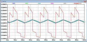
Instead of using a 50Hz sinus wave as in #502, I have connected the original Bias generator circuit to the ESL63's replacement circuit, four panels in parallel divided in 9 strips.
In the first attachment the Bias Generator's signal is visible in red, plus the resulting first 5 signals of the nine nodes in the ESL panel.
The last 4 nodes produce the same signals as the first 4 and are omitted.
The second attachment shows the same 5 nodes, but now magnified and without the Bias generator signal.
The get a steady image, the Neon bulb has been shortened.
The total 3.6nF capacity in the #502 was too high and has been reduced to 2.7nF, while the overall resistance for four panels has been kept at 6.5Meg.
Hans
Attachments

It is not unimaginable if panels develop minor leakage paths which is common in ESLs that don’t use dust covers.Well thx Steve, one thing is solved, I misread the unimaginable 100Vrms for 100mVrms 😊
It is also not uncommon for leakage paths to be present on the HV PC board after some years of operation.
The formula for calculating acoustic pressure from Force is the Walker equation shown in the image that is derived in the Baxandall chapter based on reciprocity principals, and yes the on-axis output is a function of frequency for constant applied voltage to a panel area. The ESL63 uses the delay line driven segments to spread out the sound which flattens the on-axis response. If you removed the delay lines and drove all the segments uniformly, on-axis SPL would increase at +6dB/oct with increasing frequency. This is the natural behavior of ESLs.I still have a problem to see how this could be calculated into SPL, also taking Fres of the diaphragm into account, but when assuming that the SPL with 100mVrms becomes 60dB lower, would it then go to 17.52dB ?
Once you have pressure, SPL is simply: 20*LOG10 (Pressure / Reference Pressure).
Yes, for a given Bias voltage the output scales linearly with ripple magnitude. So, 17.52dB @ 10cm for Vripple = 100mVrms.
Remember, these calculations assume low resistance diaphragm and no resistance between bias supply and diaphragm.That would likely still be above the threshold of our hearing limit, but with my ear against the ESL, and the ca. 60mV on the diaphragm that came from the simulation, I hear absolutely nothing at all?
It was just to provide you starting point to understand/quantify the effect. If resistance was accounted for, it would likely drop -20dB or more.
Added Thought
If interested in pursuing quantifying this effect on the ESL63, you can could use an audio transformer and HV capacitor to add an audio signal to the HV bias supply. You could then directly measure the SPL for a given known ripple magnitude and frequency. This is essentially how single-ended ESLs work. (see attached example of single-ended ESL tweeter)
Attachments

Last edited:
Steve,
You seemingly used a number of assumptions such as low diaphragm's coating resistance and without a 10Meg series resistance.
Let me focus on real measurements thx to Daihedz and on simulations that I made to get a feeling what ripple can be expected on a Diaphragm measuring 25Meg from side to side.
Daihedz used a 0.283V rms input signal, that will result in 64.6V rms on the stators.
When according to your calculation in #701, 5000V rms causes 93.44dB SPL, then the 64.4V rms causes 55.64dB SPL.
With ca 100mV rms ripple on the Diaphragm, sensitivity will be modulated by -94.32dB (= 20*log(100mV/5200V)) and at this level AM products will appear around a single signal such as was done by Daihedz when using a 1.5Khz tone.
So modulating this 55.64dB SPL 1.5Khz signal, with a 100mV/5200V bias ripple, would result in AM products -94.32dB down the signal's magnitude.
Unfortunately, we can't look deeper as -75dB in #676, because that's where the noise masks everything below, in fact we are already at 55.64dB SPL -75dB is at -19.36dB SPL.
But that AM sidebands even lower as -19.36dB SPL will be really there, here hidden in the noise, is a fact.
This calculation shows IMO that ripple artefacts from the Bias generator will be way below our hearing threshold, which seems to be confirmed by putting your ear to the ESL, and even at the loudest 5000V rms signal producing 93.44dB SPL, the AM products at -94.32dB down, will be still below 0dB SPL
Hans
Last edited:
I think you miss a factor of two. When you amplitude modulate a carrier with a tone, you get sideband tones above and below the signal, each having a level of half the modulation depth times the carrier.
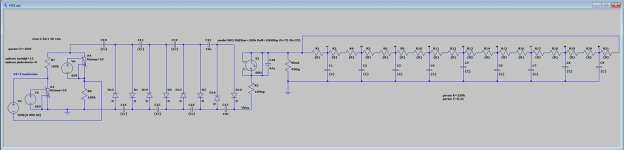
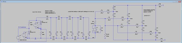
Since no further comments were given after Marcel, I have finalized the EHV model.
In #705 with the help of LTSpice, it could be shown what kind of ripple is transferred from the Bias Generator to the Diaphragm.
Remarkably the ripple was quite evenly distributed over the diaphragm.
That's why I could simplify the model with one resistor and one cap per panel, and put all four ESL63 panels in the sim.
When one panel measures 25Meg from side to side on the two diaphragm contacts, in the simplified model the can be seen as two 12.5Meg in parallel or 6.25Meg. Simulating the more complex model driven from both sides and comparing it to the simple model with just one 6.25Meg resistor gave the same ripple voltage as a confirmation.
The Audio transformer that is part of the circuit, measured a 50K Impedance per side from the stator side of the panel over a broad frequency range.
These two values are added to the model, but have practically no impact on the ripple magnitude on the Diaphragm.
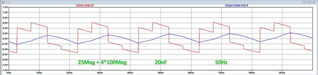
Simulations are shown for resp 10nF and 20nF caps in the bias generator, almost halving the ripple.
As a last step 100Meg resistors were inserted in each of the 4 panels, something that Demian described to have done in one of his postings.
This leads to another ripple voltage drop on the Diaphragm.
All three sims below have the same scale for a direct comparison, but the diaphragm's ripple voltage has been magnified by a factor 8 for a better view.
I have also added the .asc model for experimenting with other Diaphragm sheet resistance values.
Conclusion so far is that with the values as used here, AM products seem to be rather harmless at -100dB below signal amplitude when having 10nF caps in the bias generator.
Going to 20nF and putting 100Meg in series with each panel, another ca. 13dB improvement can even be achieved.
Hans
In #705 with the help of LTSpice, it could be shown what kind of ripple is transferred from the Bias Generator to the Diaphragm.
Remarkably the ripple was quite evenly distributed over the diaphragm.
That's why I could simplify the model with one resistor and one cap per panel, and put all four ESL63 panels in the sim.
When one panel measures 25Meg from side to side on the two diaphragm contacts, in the simplified model the can be seen as two 12.5Meg in parallel or 6.25Meg. Simulating the more complex model driven from both sides and comparing it to the simple model with just one 6.25Meg resistor gave the same ripple voltage as a confirmation.
The Audio transformer that is part of the circuit, measured a 50K Impedance per side from the stator side of the panel over a broad frequency range.
These two values are added to the model, but have practically no impact on the ripple magnitude on the Diaphragm.
Simulations are shown for resp 10nF and 20nF caps in the bias generator, almost halving the ripple.
As a last step 100Meg resistors were inserted in each of the 4 panels, something that Demian described to have done in one of his postings.
This leads to another ripple voltage drop on the Diaphragm.
All three sims below have the same scale for a direct comparison, but the diaphragm's ripple voltage has been magnified by a factor 8 for a better view.
I have also added the .asc model for experimenting with other Diaphragm sheet resistance values.
Conclusion so far is that with the values as used here, AM products seem to be rather harmless at -100dB below signal amplitude when having 10nF caps in the bias generator.
Going to 20nF and putting 100Meg in series with each panel, another ca. 13dB improvement can even be achieved.
Hans
Attachments


As has been mentioned before Quad made no real changes to the electronics with the introduction of the 6 panel speakers, what would be more appropriate values for the resistors at the end of the line, R5-8 in the ESL63, 360K
Stuart
Stuart
Marcel,I think you miss a factor of two. When you amplitude modulate a carrier with a tone, you get sideband tones above and below the signal, each having a level of half the modulation depth times the carrier.
A bit retarded reply but nevertheless.
You are right that each individual sideband is 6 dB below the modulation depth times the carrier, but in terms of unwanted additions to the original waveform, it is the sum of the anomalies that matters for audio, in this case the sum of both sidebands.
This sum is 6dB peak and on average 3dB above the level of each individual sideband.
In that case in my previous posting the level is -97.32 below the carrier, although the “breathing” of the combined sidebands may be a matter of more concern, and -94.32 would be a more safe figure to keep.
Hans
Hans, I'm a bit confused now. When asked, Steve said:
Am I missing something?
Jan
On your reply and following calculations you seem to assume the ripple is 100mVrms.2) The ripple on the HV supply is 100Vrms not 100mVrms.
Am I missing something?
Jan
Jan,
Please look at the sim in #710 and you can see what the ripple is.
With this ripple, contribution from AM modulation is below -97dB.
A 100Vrms ripple would cause AM modulation products at least 60dB higher, causing intolerable sound reproduction.
Hans
Please look at the sim in #710 and you can see what the ripple is.
With this ripple, contribution from AM modulation is below -97dB.
A 100Vrms ripple would cause AM modulation products at least 60dB higher, causing intolerable sound reproduction.
Hans
Slightly OT: I understand that the newer QUAD ESL 2805 and 2905 have different step-up transformers than the ESL 63 family derivatives.
Does anyone have info about this, in what way the newer steps-ups are different?
Jan
Does anyone have info about this, in what way the newer steps-ups are different?
Jan
I will have a repair coming in this spring... no time schedule due to working over time. I am also curious so I will def take the opportunity.

Slightly OT: I understand that the newer QUAD ESL 2805 and 2905 have different step-up transformers than the ESL 63 family derivatives.
Does anyone have info about this, in what way the newer steps-ups are different?
Jan
They are mechanically held in the base of the speakers slightly differently, but the speakers measure virtually identically, so I wouldn't expect the transformers to be significantly different.
Here's a 2805:
Here's a 63:
without the retaining cover on the 63 transformers they look very much like the 2805's:
The 2805 has a winding former and the 63 does not.
Based on a cursory exam and the fact that the speakers measure the same, I'd say the input transformers are more similar and different.
Sheldon
Thanks Sheldon, indeed they look pretty much the same aside from the coil former.
Everything else looks the same too, so it wouldn't make sense to change the transformer parameters.
Thanks for the pics.
Jan
Everything else looks the same too, so it wouldn't make sense to change the transformer parameters.
Thanks for the pics.
Jan
Yes, everything else has remained the same as far as I can tell from the latest 63's to today. That's why I tell people the best value is a set of rebuilt 63's.
I'd be shocked if they ever make changes to this design again, given that the name and design is owned by a giant audio clearing house, who doesn't have much appetite to dump resources into such a fringe product for a dying consumer base.
Sheldon
I'd be shocked if they ever make changes to this design again, given that the name and design is owned by a giant audio clearing house, who doesn't have much appetite to dump resources into such a fringe product for a dying consumer base.
Sheldon
- Home
- Loudspeakers
- Planars & Exotics
- QUAD 63 (and later) Delay Line Inductors