You regard the Bias voltage as a signal, which to my opinion is not the case because it is puts equal force to both plates.
Hans
Hans
Not if it is AC (ripple) I think.
Say each stator is 3000V, and the bias varies 200V, that gives an effectively 200V modulation on the stator-to-diaphragm voltage, which is just a signal as a modulation of the stators with constant diaphragm voltage.
Jan
Say each stator is 3000V, and the bias varies 200V, that gives an effectively 200V modulation on the stator-to-diaphragm voltage, which is just a signal as a modulation of the stators with constant diaphragm voltage.
Jan
Last edited:
You also have a huge resistance in the dissipative coating of 10^8 ohms so it does not charges directly. I have tried to listen for pops orsounds when the lamp is flickering but no...
And in between the flickering the HV is galvanically decoupled from the membrane.
But I see your point, there is room for improvement with an extra RC link...
And in between the flickering the HV is galvanically decoupled from the membrane.
But I see your point, there is room for improvement with an extra RC link...
A neon bulb starts conducting at around 90 to 100 Volt and stops conducting at between 50 and 70 volt.
So the minimal ripple on the Bias voltage is between 30 and 50 Volt.
Hans
So the minimal ripple on the Bias voltage is between 30 and 50 Volt.
Hans
1. I think Hans's estimate for the leakage resistance is way too low, even when the weather is wet.
2. The diaphragm itself filters the ripple. It has a high resistance coating to keep the charge at its place when the diaphragm moves.
3. Ideally, ripple on the polarization voltage intermodulates with the signal, so you get sidebands around the signal rather than hum. That's only partly true, though, as you will have asymmetries in real life, such as unequal distances between the diaphragm and the front and back stators.
The ripple on the bias supply will modulate the sensitivity of the speaker. You could detect it as modulation of a steady tone but even then it would be difficult. In the Crosby Quad we added 100 Meg resistors in series with each panel's bias connection to ensure constant charge operation. It worked fine. You need an electrostatic voltmeter to gauge anything about leakage etc. on the bias supplies. However subjectively, using regulated bias supplies made all the difference in the world (??). Never did AB and it was a lot of work to install. We used little EMCO modules with a regulation loop attached. They ran on 12V. Most of the power was in the voltage divider for the regulator.

1) I fully agree that the leakage resistance is much higher.1. I think Hans's estimate for the leakage resistance is way too low, even when the weather is wet.
2. The diaphragm itself filters the ripple. It has a high resistance coating to keep the charge at its place when the diaphragm moves.
3. Ideally, ripple on the polarization voltage intermodulates with the signal, so you get sidebands around the signal rather than hum. That's only partly true, though, as you will have asymmetries in real life, such as unequal distances between the diaphragm and the front and back stators.
It was just a simple calculation to get some feeling for the orders of magnitude.
But the fact that the neon bulb lights every so many seconds, thereby having a voltage drop of ca 50 Volt, can be backwards translated in 50 volt per 20 seconds with a 5nF cap, means 12.5nA or a resistance of 400GOhm.
That’s rather immense 😊
2) agreed
3) The sidebands of the modulation should most likely be inaudible because of the low level and because of being so close to the frequency they modulate.
Hans
The cap to be discharged by the Neon NE-2 bulb is 47nF.
The 5nF that I used was a factor 10 off, so the leakage resistance is 45GOhm to get a 20 sec relaxation time.
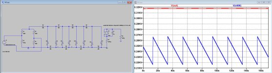
To make the picture complete, I ran a sim of the whole circuit.
Instead of a neon bulb a switch was used, closing a 100Volt, thereby discharging the 47nF cap, and opening again at 50Volt to let the 47nF cap charge again to 100Volt.
What is shown in the first image is the HV voltage in red, with a 50Hz band.
The green signal shows the current flowing into the ESL's diaphragm.
Since the current is practically constant, the HV voltage stays within a band < 1.5 Volt with a 100Hz ripple.
The second image shows the same, but now the voltage on the ELS's diaphragm is also visible in blue, having a sawtooth ripple of 50 Volt.
Hans
The 5nF that I used was a factor 10 off, so the leakage resistance is 45GOhm to get a 20 sec relaxation time.
To make the picture complete, I ran a sim of the whole circuit.
Instead of a neon bulb a switch was used, closing a 100Volt, thereby discharging the 47nF cap, and opening again at 50Volt to let the 47nF cap charge again to 100Volt.
What is shown in the first image is the HV voltage in red, with a 50Hz band.
The green signal shows the current flowing into the ESL's diaphragm.
Since the current is practically constant, the HV voltage stays within a band < 1.5 Volt with a 100Hz ripple.
The second image shows the same, but now the voltage on the ELS's diaphragm is also visible in blue, having a sawtooth ripple of 50 Volt.
Hans
Attachments


It’s obvious that the neon bulb “only” has a diagnostic function to show that the HV part is working properly, indicated by blinking every so many seconds.
The 50volt sawtooth on the Diaphragm caused by this neon bulb insertion results in no perceivable acoustic effect, despite the sharp charge ramp being 1% of the HV in magnitude.
In the sim the ramp has been tempered by giving the switch a 10 Meg resistance when on, but the discharge time by the neon bulb will most likely be much faster.
Hans
Nice result! Thanks to all above for this diversion into Bias.
So - given the massive resistivity of the diaphragm coating, that c. 1.5 ripple on c.6000v bias seems to me taht any sidebands arising will at most be c.-70dB level relative to speaker drive input.
I can live with that... !
Prompts a further thought , I don't have an intuitive 'feel' for: is the direct connection of the 47nF cap across the neon ideal - or might some added series resistance be a good idea... or is that silly, given the neon is supplied by the fairly-high source impedance of the Multiplier etc.
(I am just pondering, out-loud - how to limit hf spectrum of the change in voltage state; a dab of LPF for pyscho-acoustic reasons, perhaps. )
Last edited:
If you add too much series resistance, the neon lamp won't blink anymore.
The resistor-capacitor-neon lamp circuit has been used all over the place since at least 1927. As long as the capacitor is large enough to make it oscillate and small enough not to blow up the lamp, it works fine. The sharp edges are still filtered by the series resistance (10 Mohm and much larger diaphragm resistance) and diaphragm to stator capacitance.
(Balthasar van der Pol wrote an article about neon lamp frequency dividers in 1927, and described a phenomenon that in retrospect must have been chaos. It was the first description of chaos in an electronic circuit in history.)
The 1.5V ripple is before the neon bulb.Nice result! Thanks to all above for this diversion into Bias.
So - given the massive resistivity of the diaphragm coating, that c. 1.5 ripple on c.6000v bias seems to me taht any sidebands arising will at most be c.-70dB level relative to speaker drive input.
I can live with that... !
Prompts a further thought , I don't have an intuitive 'feel' for: is the direct connection of the 47nF cap across the neon ideal - or might some added series resistance be a good idea... or is that silly, given the neon is supplied by the fairly-high source impedance of the Multiplier etc.
(I am just pondering, out-loud - how to limit hf spectrum of the change in voltage state; a dab of LPF for pyscho-acoustic reasons, perhaps. )
The Diapragm is confronted with a 50 V sawtooth.
But you cannot simply translate that into a sideband calculation without knowing the transfer function.
The voltage applied to the diaphragm must be seen as a CM signal whereas the plates are working in DM.
CM suppression is very good, but has its limits because of (mechanical) imperfections.
But sensitivity is affected by a changing bias voltage and this amplitude modulation causes sidebands.
See image in #539 where amost reducing the Bias voltage by a factor two, results in a loss of sensitivity of 1.7 dB.
Quad would never have inserted this diagnostic neon bulb in the bias line, when it would have resulted in a perceivable sound detoriation.
But you can take the proof of the pudding, shorten the neon bulb and listen to the difference in sound, if any.
In that case the diaphragm will only see 1 Volt ripple instead of the 50V sawtooth.
Hans
I've no desire to 'short' the neon bulb, or touch the bias side at all, for obvious reasons... it was a small, distracting, musing .
Thank-you both, @MarcelvdG & @Hans Polak - for fast and informed responses, as ever.
More for me to digest ; )
Thank-you both, @MarcelvdG & @Hans Polak - for fast and informed responses, as ever.
More for me to digest ; )
See attachment for a mains supply of resp 225V and 140Volt that translates directly proportional to the HV Bias Voltage
You assume the bias voltage to be proportional to the mains voltage, but as far as I know, the VDR in the ESL-63 is supposed to provide a crude form of voltage regulation. Maybe that's why you get only 1.7 dB of level change instead of 20 10log(225/140) dB.
A 50 V peak-peak, 0.05 Hz ripple on a 5250 V high voltage supply should make the volume go up and down by a bit less than 1 %, or 0.08 dB, every 20 seconds. I certainly never noticed that, and I doubt if anyone else ever did, but if you want to avoid all easily avoidable artefacts, you should short the neon lamp. (Spectrally, it causes sidebands of about -46 dB, but at only 0.05 Hz frequency offset.)
Last edited:
Marcel, Interesting comment, I have no information about those VDR’s and would be a bit surprised if they could correct such a large input voltage change, but who knows ?
My feeling was that those VDR’s where meant to prevent the bias getting too high, coming in action at a much later state as you suggest.
Maybe someone can comment on that, if not it will be easy to measure.
Hans
My feeling was that those VDR’s where meant to prevent the bias getting too high, coming in action at a much later state as you suggest.
Maybe someone can comment on that, if not it will be easy to measure.
Hans
I think Peter Baxandall wrote about it in his chapter about electrostatic loudspeakers in John Borwick's Loudspeaker and Headphone Handbook.
Marcel,
The transformer is producing 600Vrms and the VDR is a S10K460 that clamps at 460Volt.
Taking the latest version of the Bias generating circuit in the sim below, with 600Vrms input, Bias voltage becomes 5.32KV.
Any higher and the VDR will start clamping.
Lowering the 225Volt to 140Volt will result in a bias voltage of 3.36KV or 4.0dB less Bias voltage.
This resulted in 1.7dB less sensitivity, not 4.0 dB.
Hans
Attachments

Rather elementary physics show that the sound pressure level should be directly proportional to the polarization voltage of the diaphragm, so there must be something going wrong somewhere.
There are several revisions of the ESL 63 electronics. Is the version you simulated the same as in the ESL 63 of which you measured the level?
How did you model the VDR or the two VDRs? There only appear to be linear resistors in your schematics.
There are several revisions of the ESL 63 electronics. Is the version you simulated the same as in the ESL 63 of which you measured the level?
How did you model the VDR or the two VDRs? There only appear to be linear resistors in your schematics.
I used a resistor, but I could also have inserted a Zener of 460Volt.
As I mentioned I simulated the latest version of the Bias generator having only one VDR.
The resistor respresenting the VDR in this case was set at a very high resistance value.
And at 600Vrms, the voltage on the VDR is indeed +/-460V peak, anything higher will be clamped.
So at 140V input , the VDR it is not conducting at all and bias voltage will drop by 4dB.
The acoustic measurements I did, may be +/- 0.1dB off, but certainly not the 2.3dB difference between 1.7dB and 4.0dB we see here.
Hans
I'm not sure that holds actually. For a single ended transducer that seems correct. The speakers are push-pull which alters the relationships. Conceivably as long as the bias is higher than the peak voltage the sensitivity should not change. That may also be a naïve understanding of the physics. In my experiece the net change in output with different bias voltage is pretty small and nonlinear BUT it did seem to have an impact on the frequency response, albeit small as well."Rather elementary physics show that the sound pressure level should be directly proportional to the polarization voltage of the diaphragm, so there must be something going wrong somewhere."
- Home
- Loudspeakers
- Planars & Exotics
- QUAD 63 (and later) Delay Line Inductors