I have this kind of "Christmas tree" adapter in one of my boxes. I tried once. A real antenna et very fragile. 😉
Especially since in Tibi's version, there is no LFE as input.
Stef.
Especially since in Tibi's version, there is no LFE as input.
Stef.
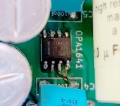
I have desolder the opamp adapter with hot air flow and C6 was inflated for hot air blowing ..so I changed C6 with new cap.
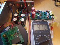
I soldered OPA1641 directly on the pcb and powered it up.
It showed dc offset 41V. It seems that problem becomes more bigger than before.
I soldered OPA1641 directly on the pcb and powered it up.
It showed dc offset 41V. It seems that problem becomes more bigger than before.
Attachments
Q17.2 version
https://github.com/tiberiuvicol/Q17-audiophile-amplifier
R32 is 10R on silkscreen of pcb but is 0R on schematic.
Which is correct?
https://github.com/tiberiuvicol/Q17-audiophile-amplifier
R32 is 10R on silkscreen of pcb but is 0R on schematic.
Which is correct?
Hello,
By default R32 = 10R.
R32 is the HBR resistor (Hum Breaking Resistor). Depending on the wiring and ground loops, this resistor can vary from 0R to 10R (the minimum value being 0R1). Without this resistor or a strap, the amp cannot function.
The output offset will vary depending on the resistor value. Less than 1mV with 0R and 37mV with 10R.
Stef.
Last edited:
It's solid. I've already connected several of them upside down by mistake (on a DIP socket, it's easy to get confused). They survive.
Maybe.
But this one will be hit a minimum of three times with hot air. Probably good to have a few backups😉
But this one will be hit a minimum of three times with hot air. Probably good to have a few backups😉

Never solder smd with heat gun, either use oven, plate or best for smd large as this soldering iron (without stencil, it may be the best option, you don't risk soldering balls this way).
When you burn it on an already assembled board, you have to change it as this. 😉
I use a 180°C paste. It's ok and fast.
Stef.
I use a 180°C paste. It's ok and fast.
Stef.
Thank you all!
The direction of trying opamps was opposite direction.
I desoldldered the opamp and soldered the right direction and powered it up.
It showed dc offest over 20V.
Maybe C3, C6 or opamp was demaged
I will try new caps and opamp.
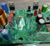
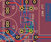
BTW... is polarity of C3 and C6 like this?
The direction of trying opamps was opposite direction.
I desoldldered the opamp and soldered the right direction and powered it up.
It showed dc offest over 20V.
Maybe C3, C6 or opamp was demaged
I will try new caps and opamp.
BTW... is polarity of C3 and C6 like this?
Attachments


Easy fix, desolder cap, solder it from below, and bypass track with thin wire to the leg of the cap.
@Brijac
Thank you for guiding me!
I saw the soldered C3, C6 caps on Q17 double output board on this github (
https://github.com/tiberiuvicol/Q17-audiophile-amplifier).
....so I thought the polarity on single output board same as it.
So foolish .......
Thank you for guiding me!
I saw the soldered C3, C6 caps on Q17 double output board on this github (
https://github.com/tiberiuvicol/Q17-audiophile-amplifier).
....so I thought the polarity on single output board same as it.
So foolish .......
- Home
- Amplifiers
- Solid State
- Q17 - an audiophile approach to perfect sound