Hello,
Yes, I no longer have any worries.
This was a bit complicated to solve because I had 3 differents problems at the same time (bad toroid, bad first psu PCB and bad connectors). The most important problem came from the connectors because I had insufficient/bad contact, so the GND was trying to find others routes to circulate including the GND of the RCA connectors when a source was connected.
Since I switched to Faston connectors, I can have fun moving the power cables without it producing hum. I move them around in the box and even pass them between the toroid and the PSU, above the Q17 board without it changing anything.
When wiring, it is better to set R32=0R (J4 jumper). This allows you to hear even the slightest hum (use headphones or high sensitivity speakers) and to optimize your cabling. Afterwards, we can put R32=10R back but it depends on the sensitivity of the speakers.
Stef.
Last edited:
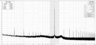
To complete, here are the spectrums of the two voices of the boxed Turbo 1.2.3.
The left voice keeps a greater trace of the hum. It's the one next to the power outlet. I'll have to see if I can improve this but it's inaudible with regular sensitivity speakers.
Stef.
The left voice keeps a greater trace of the hum. It's the one next to the power outlet. I'll have to see if I can improve this but it's inaudible with regular sensitivity speakers.
Stef.
Attachments


Hello Stef,
now the diagram of your meter when the inputs are coupled is missing - that is the noise floor of the meter, so that we can see what else can be from the amplifier and what the meter shows anyway.
Tim
now the diagram of your meter when the inputs are coupled is missing - that is the noise floor of the meter, so that we can see what else can be from the amplifier and what the meter shows anyway.
Tim
I only have one output and one input on my measurement system. I can't watch both channels at the same time.
Stef.
Stef.
Hi Q17 adepts!
Does, next to Tim's unstoppable effort, exist a single pair version including the latest mods? Can't find it anywhere.
My first build was a single paired , but I have re-used the parts for the double one. The Tibi version Q17.2 one year ago.
I regret a little I did that, because in my setup I was happier with the way that first one sounded. (better base and slightly smoother treble and low level playing). All by remembering btw.
Bonjour Stephane!
I am afraid my sight/bon sens is not of high quality anymore. This is what I am looking for trying again. Do you have a set of boards left to share?
Thanks anyhow.
Ed
I am afraid my sight/bon sens is not of high quality anymore. This is what I am looking for trying again. Do you have a set of boards left to share?
Thanks anyhow.
Ed
Hello,
This is just to tell you that I was finally able to test the Q17-Turbo 1.2 clip with a new, much more powerful test 8R resistor.
The clip occurs just a little above 34vRMS with an input voltage of 60vDC, which corresponds to 150W @ 8 Ohms.
Regards,
Stef.
This is just to tell you that I was finally able to test the Q17-Turbo 1.2 clip with a new, much more powerful test 8R resistor.
The clip occurs just a little above 34vRMS with an input voltage of 60vDC, which corresponds to 150W @ 8 Ohms.
Regards,
Stef.
Hello Stef,
If your turbo starts clipping so early, you should start troubleshooting, as the circuit can deliver significantly higher power.
A limitation will result from the inductance of the large capacitors, simplified, the ESR. Your transformer cannot have a higher internal resistance at this power, as it is only loaded with around 200W.
Will you also test the Mini to see if it starts clipping later? The current of just 4.3A is still low for the installed MosFET.
Regards Tim
The resistance is not of very good quality. It is a classic 150W metal resistor. I plan to buy large, quality thick film resistors later when I have an order to place at Mouser.
For the test, I did not use a transformer but a laboratory power supply which is limited to 60V/3A. I was at around 2.5A per power channel at the time of the clip.
Stef.
For the test, I did not use a transformer but a laboratory power supply which is limited to 60V/3A. I was at around 2.5A per power channel at the time of the clip.
Stef.
Hello Stef,
then you should write that your test setup starts clipping at 150W output and not the turbo.
Regards Tim
then you should write that your test setup starts clipping at 150W output and not the turbo.
Regards Tim
Hello,
I have used my level meter NTI XL2 as an electrical analyzer and I have realized the following setup:
DAC with output level of 108mV (90Hz), input potentiometer from Q17 and at the output 80mV level (load resistor 15Ohm).
The measured noise floor of the amplifier is approx. 1.5µV, the 50Hz mains hum is 38 µV.
My aim is to find out how quiet the amplifier is. The level meter is even more sensitive, its noise floor is below 100nV. The level meter was also just calibrated at the factory, so it won't measure that much wrong.
I measure 0.01% THD for the DAC and 0.2% THD for the Q17. What exactly the level meter measures and evaluates is less clear. In the FFT, the 2nd harmonic was approx. 80 µV with the current setup and even lower with version 13 of the Q17.
Regards Tim
Gentlemen!
I've been following this conversation for a long time and have already recreated some of it.
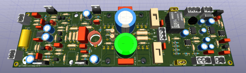
My last project was that I put together the Q17 turbo with a speaker protection circuit.
Thank you for the professional contributions
I've been following this conversation for a long time and have already recreated some of it.
My last project was that I put together the Q17 turbo with a speaker protection circuit.
Thank you for the professional contributions
Attachments

Hello everyone,
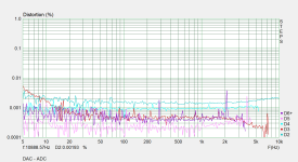
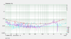
Today, I received a used Tecam USB Interface, and I conducted a distortion analysis for the amplifier at room volume using Arta Steps. I created two diagrams: one without the amplifier and another with the amplifier. I made sure that the levels at the DAC and the ADC were equally high and tested them first to capture their minimal distortions.
Best regards,
Tim
Attachments
Gentlemen!
I've been following this conversation for a long time and have already recreated some of it.
My last project was that I put together the Q17 turbo with a speaker protection circuit.
Thank you for the professional contributions
Hello,
Nice idea.
You can probably update the PCB to Turbo version 1.2.3 and remove the fuses. Also try to reduce the length of the board. The board seems really long to fit into standard boxes.
Why are there two connectors on the Input side?
Good luck.
Stef.
Hello Steff,Hello!
I have released a new version of the Q17-Mini PCB with some improvements.
Have a good day,
Stef.
Q17-Mini-1.1.2 release
- New vertical footprint for coil
- New SMD footprints on back PCB
- Update C7/R18 circuit position
- Some tracks optimisation
- New 3D and PCB pictures
- Archived version 1.1.1
https://github.com/stefaweb/Q17-a-QUAD405-audiophile-approach
I had Q17 Mini 1.1.2 v pcb a long time ago. I can't find the schematic. Can you e-mail me the 1.1.2 ver schmatic ? I can't find it on Github.
fazildiken@gmail.com
Hi,
The files from the old versions are in the archives directory.
https://github.com/stefaweb/Q17-Amplifier/tree/main/Q17-Mini Archives
Versions of the Q17-Mini below 1.3 are not as good.
Regards,
Stef.
The files from the old versions are in the archives directory.
https://github.com/stefaweb/Q17-Amplifier/tree/main/Q17-Mini Archives
Versions of the Q17-Mini below 1.3 are not as good.
Regards,
Stef.
Thanks Stef!
When the board is mounted vertically on the heat sink. Normally the connections are at the top or bottom.
I don't like that, I like symmetry
Of course you can still optimize the board and make it shorter.
I have a device depth of 350mm, so it fits
When the board is mounted vertically on the heat sink. Normally the connections are at the top or bottom.
I don't like that, I like symmetry
Of course you can still optimize the board and make it shorter.
I have a device depth of 350mm, so it fits
- Home
- Amplifiers
- Solid State
- Q17 - an audiophile approach to perfect sound